background image

PRESTO OWNER’S MANUAL        

 Page 17

          POWER STAK 

Figure 4:  Steering Component

Item Description

Qty

1

Drive wheel Assy

1

2

Spindle Assy

1

3

Spring Washer

4

4

Bolt

4

5

Seal

1

6

Bearing

1

7

Spindle Seat

1

8

Bearing 

1

9

Bolt

4

10

Spring Washer

4

11

Washer

1

12

Fixing Board

1

13

Bolt

2

14

Collar Spindle

2

15

Lock Nut

1

Item Description

Qty

16

Seat Connection

1

17

Bolt

2

18

Anchor Spindle Cover

1

19

Lock Washer

1

20

Nut

1

21

Spindle Cover

1

22

Screw

2

23

Spring Washer

2

24

Nut

2

25

Micro Switch

1

26

Bolt

2

27

Snap Ring

1

28

Spindle Collar

2

29

Air Spring

1

30

Fixing Shaft

1

31

Control Handle

1

32

Anchor Handle

1

33

Control Pod

1

34

Bolt

3

35

Flat Key

1

Summary of Contents for Power Stak PPS2200-150AS

Page 1: ...______________ Serial ____________________________________________ Date Placed in Service _____________ IMPORTANT READ CAREFULLY BEFORE INSTALLING OR OPERATING LIFT December 2018 This manual covers PowerStak units with frame numbers starting with GC stamped into the mast and shipped March 2014 and after ...

Page 2: ...ility of the buyer and must be accompanied with an RGA number The shipping charge to return the component to the buyer is the responsibility of Presto Lifts Inc This limited warranty does not cover labor expense for removal or reinstallation of components after thirty days This limited warranty shall not cover among other things damages resulting from foreign matter or water failure to provide rea...

Page 3: ...2 B Charging the battery 12 C Warnings and Battery Info 12 D Battery maintenance 12 E Charger Operations 12 S E C T I O N 6 Maintenance 13 A Weekly Operations Maintenance Checks 13 B Monthly Operations Maintenance Checks 13 S E C T I O N 7 Troubleshooting 14 ORDERING REPLACEMENT PARTS 28 RESTOCKING POLICY 29 LIST OF FIGURES Figure 1 Operational Buttons 10 Figure 2 Stacker Body Components 15 Figure...

Page 4: ...ROCEDURE FOR POWERSTAK STRADDLE LEGS NOTE STRADDLE LEGS MUST BE ADJUSTED IN ACCORDANCE WITH THIS PROCEDURE 1 PowerStak unit located on flat clean uniform surface unloaded forks raised a minimum of 1 off the floor 2 Determine the desired required straddle width dimension 2 inches greater than pallet width 1 on each side of the pallet or load up to a maximum of 50 inches inside width 3 Be sure to fu...

Page 5: ...N THIS MANUAL CALL PRESTO LIFTS FOR FURTHER INSTRUCTIONS The battery operated stackers are designed for in plant non hazardous locations only They can be used in a 8 or larger aisle These units are not for personnel lifting WARNING Maximum Lifting Capacity UP TO 7 2 200 LBS UP TO 8 1 800 LBS UP TO 10 1 500 LBS Ratings based on 24 Load Center See Owner s Manual for details 10055256 This machine is ...

Page 6: ...ctions Operators Only trained personnel and authorized personnel shall be permitted to operate PowerStak Before Operation Before using the device the operator shall have Read and or had explained and understood the manufacturer s operating instructions and safety rules Inspected the device for proper operation and condition Any suspect item shall be carefully ex amined and a determination made by ...

Page 7: ...equences which may occur if instructions or precautions are not followed Below are the symbols and signal words along with their definitions referenced from ANSI Z535 4 Product Safety Signs and Labels Safety Alert Symbols These are the safety alert symbols They are used to alert you to potential physical injury haz ards Obey all safety messages that follow this symbol to avoid possible injury or d...

Page 8: ...p the stacker under control at all times Oper ate at a speed that allows you to stop safely Be even more careful on slippery or uneven surfaces Do not run over objects on the floor Perform all stacker movements smoothly and at a speed that will give you time to react if an emergency occurs Tipovers and falls are very serious accidents you can be crushed or even killed To prevent injury know where ...

Page 9: ... to your carrier and your Presto dealer immediately Remove all metal plastic bands cardboard and other material used for shipping purposes Check to see if chains are in place and that the lift system is in working order Inspect for oil leaks Connect battery cable Check cables and wires on battery charger as well as battery Note The travel speed is preset at the factory For travel speed adjustment ...

Page 10: ...rection of the motor will slow down stop and reverse the direction of stacker When parked the handle will spring back to the full vertical posi tion with the brake applied and the forks in lowered position Reversing Safety At the end of the handle there is a large red reversing bar belly button switch that is designed to protect the operator from injury When the operator runs the stacker backwards...

Page 11: ...roper Charge Level before operating unit 2 Check to be sure Charging Cord is Unplugged and properly stowed before operating unit 3 Inspect Battery Wire Connections All connections should be tight with No Corrosion white powder showing at the Battery Terminals 4 Inspect Battery Case There should be no cracks or visible damage to the Battery Case WALK AROUND INSPECTION 1 Check general condition of S...

Page 12: ...hese components wear a face shield or other suitable protective eyewear Read understand and follow all battery and bat tery manufacturer s specific precautions while working with and or charging batteries D BATTERY MAINTENANCE To measure the voltage use a digital voltmeter DC on the battery poles The truck must not have been in use for the previous 30 minutes DANGER Never alter the AC cord or plug...

Page 13: ...e that they are in place and not loose FORKS Check that they are not bent or cracked BRAKE Ensure the brake works properly CABLES WIRES Check that there are no loose cables or wires LABELS Ensure all precautionary labels and guards are in place B MONTHLY OPERATIONS MAINTENANCE CHECKS 1 Battery maintenance free A Clean terminals B Clean battery compartment area if there are signs of corrosion 2 Hyd...

Page 14: ...rushes in pump motor Low hydraulic pressure caused by Pressure relief valve needs adjustment Pump check valve stuck open Faulty solenoid valve Faulty wiring from lift switch to solenoid Faulty lift contactor Defective control circuit fuse Chain or roller bound Check oil level 2 Forks will not lower Look for binding in chains or rollers 3 No electrical power Dead Batteries Keyswitch on OFF position...

Page 15: ...4 4 Spindle 2 5 Bolt 4 6 Straddle Leg LH 1 7 Nut 10 8 Bolt 10 9 Bolt 2 10 Seat 1 11 Drive Wheel Cover 1 12 Rear Cover 1 Item Description Qty 13 Screen 1 14 Straddle Leg RH 1 15 Screen 1 16 Top Cover 1 17 Stacker Body Assembly 1 18 Screw 14 19 Caster Assembly 1 20 Bolt 4 21 Spring Washer 4 22 Nut 4 23 Bracket 4 24 Bolt 4 ...

Page 16: ...Lifting Switch 2 2 Lowering Switch 2 3 Running Switch 1 4 Emergency Reverse Switch 1 5 Horn Button 1 Figure 3 Control Pod Item Description Qty 1 Lifting Switch 2 2 Lowering Switch 2 3 Butterfly Switch 1 4 Belly Button Stop Switch 1 5 Horn Button 1 6 Turtle Speed Switch 1 6 Control Pod Bottom ...

Page 17: ...g Washer 4 11 Washer 1 12 Fixing Board 1 13 Bolt 2 14 Collar Spindle 2 15 Lock Nut 1 Item Description Qty 16 Seat Connection 1 17 Bolt 2 18 Anchor Spindle Cover 1 19 Lock Washer 1 20 Nut 1 21 Spindle Cover 1 22 Screw 2 23 Spring Washer 2 24 Nut 2 25 Micro Switch 1 26 Bolt 2 27 Snap Ring 1 28 Spindle Collar 2 29 Air Spring 1 30 Fixing Shaft 1 31 Control Handle 1 32 Anchor Handle 1 33 Control Pod 1 ...

Page 18: ...er 1 5 Shaft Gear 1 6 Bearing 2 7 C Clip 1 8 Electric Brake 1 9 Bearing 1 10 Key 2 11 C Clip 1 12 Gear 1 13 Screw 4 14 Flange 1 Item Description Qty 15 Screw 3 16 Bearing 1 17 Seal 1 18 Ring Gear 1 19 Wheel 1 20 C Clip 1 21 Seal 1 22 Ring 1 23 Traction Motor 1 24 Dust Ring 1 25 Screw 10 26 Screw 3 27 Spacer 1 28 Panel 1 ...

Page 19: ...WER STAK Figure 6 Carriage Assembly Item Description Qty 1 Block 4 2 Roller 4 3 Washer 4 4 Bolt 4 5 Fixed Pin Chain 1 6 Load Bracket Assembly 1 7 Snap Ring 2 8 Feed Shaft 1 9 Bolt 2 10 Nut 2 11 Fork Assembly 2 12 Cotter Pin 2 13 Nut 4 ...

Page 20: ...1 Spring Washer 4 12 Washer 4 Item Description Qty 13 Spring Pin 2 14 Chain Wheel Cover 1 15 Bolt 1 16 Spring Washer 1 17 Washer 1 18 Chain Wheel 2 19 Snap Ring 2 20 Chain Wheel Seat 1 21 Rubber Spacer 1 22 Lift Cylinder 1 23 Bolt 2 24 Spring Washer 2 Item Description Qty 25 Washer 2 26 Plug 2 27 Bearing 2 28 Dust Cover 2 29 Spacer 2 30 Chain Assembly 1 31 Nut 4 32 Bolt 1 33 Nut 4 34 Orientation P...

Page 21: ...tion 1 11 Oil Filter 1 12 Oil Tank Plastic 1 12A Bolt Spring Washer 4 12B Cover Oil Tank 1 STACKER BODY COMPONENTS PPS2200 62NFO 21 Item Description Qty Item Description Qty 1A Valve Block 1 6C Bolt Spring Washer 2 1B Relief Valve 1 7 O Ring 1 1C Unilateral Valve 1 8 Gear Pump 1 2 Throttle Valve 1 8A Bolt Spring Washer 4 3 Solenoid Valve 1 9 Oil Hose Return 1 4A Screw Plug Metal 1 10 Oil Hose Suct...

Page 22: ... Screw 2 2 Washer 2 3 Hydraulic Assembly 1 4 L Adaptor 1 5 O ring 1 6 Oil Hose 1 7 Adaptor 1 HYDRAULIC SYSTEM PPS2200 62NAS Item Description Qty 1 Screw 2 2 Washer 2 3 Hydraulic Assembly 1 4 L Adaptor 1 5 O ring 1 6 Oil Hose 1 7 Adaptor 1 Figure 9 Hydraulic System ...

Page 23: ...PRESTO OWNER S MANUAL Page 23 POWER STAK Figure 10 Hydraulic Schematic ...

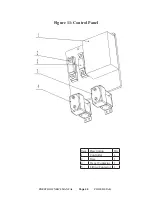
Page 24: ...OWER STAK CONTROL PANEL Item Description Qty 1 Controller 1 2 Fuse 1 3 Fuse 1 4 Travel Contactor 1 5 Lifting Contactor 1 Item Description Qty 1 Controller 1 2 Fuse 1 4 Travel Contactor 1 5 Lifting Contactor 1 Figure 11 Control Panel ...

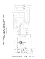
Page 25: ...PRESTO OWNER S MANUAL Page 25 POWER STAK Figure 12 Electric Schematic Diagram 24 Volt System Two 12 Volt Batteries Connected in Series Prior to November 2017 ...

Page 26: ...PRESTO OWNER S MANUAL Page 26 POWER STAK Figure 12 Electric Schematic Diagram 24 Volt System Two 12 Volt Batteries Connected in Series From November 2017 to Present ...

Page 27: ... 24VDC SPECIFIED 8 PRESTO LIFTS DWG NO UNLESS OTHERWISE 80006 5 0 00 LB 1 1 DIMENSIONS ARE IN LIMITED TO WRITTEN AGREEMENT DR PowerStak TITLE SIZE CK A DWG NO FRACTIONS 1 XXX 005 XX 01 ANGLES 3RD ANGLE v 14 B CHARGER BATTERY CHARGER CONNECTING BATTERY BATTERY CHARGER 120 VAC 24 VOLT SYSTEM 1 NEGATIVE CABLE B POSITIVE CABLE 2 B CABLE BATTERY REVISIONS REV DESCRIPTION DATE REVISE MAIN POSITIVE BATTE...

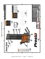
Page 28: ...EA 1 4 PLACE UPSIDE DOWN ON INSIDE OF HANDLE 2 PLACE DECAL HORIZONTAL ON CROSS BAR 3 5 7 8 SIDE OF WIDE MAST LOCATE 1 ON EACH SIDE OF WIDE MAST LOCATE 1 ON EACH 6 LOCATE 1 ITEM 6 ON MACHINE FRAME UNDER COVER 6 10039877 1 1 EA BK LD DCL 2 25X8 50 WARNING USERS MUST 10039876 ITEM NO QTY U M DESCRIPTION PART NO 8 2 EA BK LD LBL 3 00X7 00 WARNING 10055253 7 1 EA LD DCL 2 00X3 25 CAPACITY 2200 LBS AT 2...

Page 29: ...lacement parts please call the Presto Parts Department Parts are shipped subject to the following terms FOB factory Returns only with the approval of our Parts Department Credit cards preferred except parts covered by warranty Freight collect for truck except parts covered by warranty Freight prepaid and invoice for small parcel shipments except parts covered by warranty Parts replaced under warra...

Page 30: ...o Lift Inc reserves the right to determine potential credits as a result of factory defects based on its inspection of the merchandise GENERAL All products shipped from our factory have passed Quality Assurance inspection and testing The carrier of choice has signed for and accepted the product in new working condition The customer should inspect to ensure it is not received damaged has no conceal...

Reviews: