


28
Presto Lifts
PDL Manual
9.
Hydraulic Information
9.1
Hydraulic Fluid Specifications
This machine is supplied with Conoco Ecoterra Hydraulic Fluid.
Do not substitute! Conoco Ecoterra Hydraulic oil is not compatible with
oils containing Zinc. Mixing will result in poor machine performance,
could damage hydraulic components, and will lessen the environmental
benefits gained by using Conoco Ecoterra Hydraulic Oil.
9.2
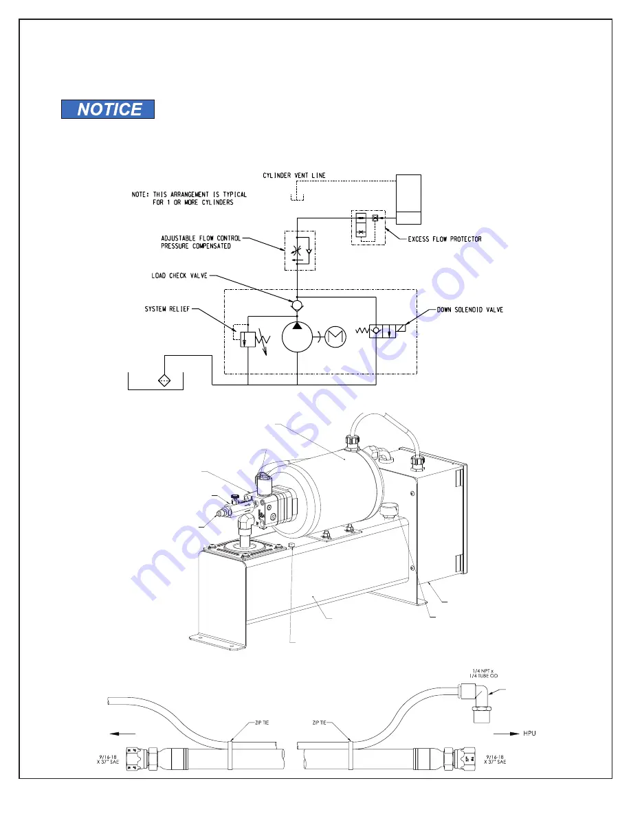
Hydraulic Schematic
9.3
Hydraulic Power Unit
9.4
Hose Specifications
ADJUSTABLE FLOW
TO LIFT
BREATHER
CONTROL PANEL
PUMP
PRESSURE LINE
MOTOR
DOWN SOLENOID/ VALVE
CONTROL
REMOVE PLUG AND REPLACE WITH VENT
LINE ELBOW AND CONNECT VENT LINE BETWEEN
LIFT VENT LINE FITTING AND THIS ELBOW.
RESERVOIR
(CAPACITY: APPROXIMATELY
2.4 US GAL.)
Minimum operating pressure rating 3,050 psi, 12,200 psi burst pressure.
Pressure hose is optional. Units supplied with 25 feet of vent line and
the hydraulic power unit vent line connection elbow if pressure hose not
purchased other wise the vent line comes in the same length as the
pressure hose.
TO VENT LINE
CONNECTION ON LIFT
VENT LINE
ELBOW FOR
RESERVOIR