Prestige Prestige 07S3BP Installation Manual Download Page 1

128-8111

1 of 20

The select

able features can be set manually as explained below

, or with the RF feature programmer

.

T

o

 set features using the RF programmer

, follow the instructions p

a

ckaged with the programmer

.

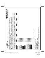
Factory default settings are indicated by bold text.

Note :

 The method of manual override can either be selected to operate from the valet switch or operate as custom code.

Be certain to place a check mark indicating the method used in the box located on the last page of the owner's manual.

NOTE: Keyless Entry Models with no horn output will Flash the Parking Lights instead of chirp where chirp is indicated.

Also, No data will be indicated if a feature is not available for a particular model.  The unit will enter the feature but no s

election will be available.

RF Programmable Feature Bank 1 Is For T

ransmitter Programming See T

ransmitter Programming Guide.

RF Programmable Features Bank 2 Is Alarm Selectable Features:

Feature Selection

1 Chirp

2 Chirps

3 Chirps

4 Chirps

5 Chirps

6 Chirps

1st DoorL/UL

1 Sec.

3.5 

Sec.

1 Sec L, Dbl. U/L

Dbl L, 1 Sec UL

Dbl 

L, 

Dbl 

UL

l/350mS 

ul

2nd 

Accy Lock

Not Available

3rd 

Accy

. UL

Not Available

4th Headlights

Not Available

5th Passive Locks

Not Available

6th Pass/Act 

Arm

Not Available

7th Siren/Horn

Not Available

8th Horn Chirp

Not Available

9th O/R Method

Not Available

10th 2 S

tep U/L

Not Available

1

1th Chp Del 

Tx

Not Available

12th V

olt

age/Hd W

ire

Not Available

13th Trigger Circuits

Not Available

14th Lock/Unlock Poll

Not Available

15th 

Aux Ch 5 Sel

Not Available

16th 

Aux Ch 6 Sel

Not Available

17th 

Aux Ch 7 Sel

Not Available

18th Trigger Delay

Not Available

When using the RF programmer

, enter the program mode as follows:

Turn the ignition on

Press and release valet switch 3 times

turn ignition off then on

Press and hold valet switch for 5 seconds

Siren and or lights chirp/flash 2 times indicating access to RF feature program mode.

Model APS-57a

Installation Manual

From APS57 Change Transmitters To 07S3BP 5/07

Summary of Contents for Prestige 07S3BP

Page 1: ...res Bank 2 Is Alarm Selectable Features Feature Selection 1 Chirp 2 Chirps 3 Chirps 4 Chirps 5 Chirps 6 Chirps 1st DoorL UL 1 Sec 3 5 Sec 1 Sec L Dbl U L Dbl L 1 Sec UL Dbl L Dbl UL 1 S l 350mS ul 2nd Accy Lock Not Available 3rd Accy UL Not Available 4th Headlights Not Available 5th Passive Locks Not Available 6th Pass Act Arm Not Available 7th Siren Horn Not Available 8th Horn Chirp Not Available...

Page 2: ...fth Press and release the valet switch Non Functional On This Unit or Sixth Press and release the valet switch Non Functional On This Unit or Seventh Press and release the valet switch Non Functional On This Unit or Eighth Press and release the valet switch Non Functional On This Unit or Ninth Press and release the valet switch Non Functional On This Unit or Tenth Press and release the valet switc...

Page 3: ...th Temp Start Not Available 14th Crank Averaging Averaging Preset Time Note When averaging the engine must be started 4 times with the key to be effective 15th R S Shock Not Available 16th Turbo Select Not Available 17th Black Blue Aux O P Single Pulse As Feature 1Bank 2 Note When setting feature 17 to operate as feature 1 Bank 1 the transmitter will also control this output only while running und...

Page 4: ...sory Press transmitter Lock button to change 1 chirp ign 3 off during crank or Ninth Press and release the valet switch 1 chirp diagnostics off Press transmitter Lock button to change 2 chirps diagnostics on or Tenth Press and release the valet switch 2 chirps crank time 1 0 sec Press transmitter Lock button to change 3 chirps crank time 1 5 sec Press transmitter Lock button to change 4 chirps cra...

Page 5: ...aths If necessary the included brackets may be used to move the hood pin switch away from rain gutters or allow mounting to the firewall behind the hood seal In either case the hood pin switch must be set up to allow the hood to depress the switch at least 1 4 when the hood is closed and fully extended when the hood is opened For direct mounting a 1 4 hole must be drilled Carefully check behind th...

Page 6: ...provides power for the control circuit as well as the ignition 1 and ignition 2 relays Fused RED WIRE 12 Volt Battery 2 Source Locate the vehicle battery wire s at the ignition switch Verification These wires will register voltage in all positions of the ignition switch Connect the Red wire to the vehicle s battery wire This wire provides power for the start relay and the accessory relay I M P O R...

Page 7: ...itch This wire will show 12 volts when the ignition key is turned to the to the ON or RUN and the START or CRANK positions and will have 0 volts when the key is turned to the OFF and ACCESSORY positions For Diesel Applications this wire must be connected to the ignition circuit that powers the glow plugs if the vehicle requires glow plug pre heating GREEN WIRE Ignition 2 Output Connect this wire t...

Page 8: ...ERWIRE NegativeInhibitInput2 Any time the gray w black tracer wire is grounded the Remote Starter will stop operating even if the signal is received from the transmitter If the brake light switch in the vehicle switches ground to the brake light circuit connect the Gray w Black trace wire to the output of the brake light switch If the brake light switch in the vehicle switches 12 Volts do not use ...

Page 9: ...ing Light Flasher These wires are the COMMON and NORMALLY OPEN contacts of the on board parking lamp relay If the vehicle s parking lights are a 12 volt switched system connect 1 of the White wires to a fused 15A max 12 volt battery source and connect the second White wire to the vehicle s parking light wire If the vehicle s parking lights are a chassis ground switched system connect 1 of the Whit...

Page 10: ...hin gauge wires running from the ignition switch to the VATS control module NOTE These wires are typically White w Black trace and Violet w Yellow trace however in later model Cadillacs they are run through an orange sleeve and are either both Black both Yellow or both White wires Consult the factory service manual for additional information 3 Connect the Light Blue Wire from the Remote Start Unit...

Page 11: ...ft deterrent system to prevent false triggering of the factory alarm when the remote start unit engages or when the transmitter is used to unlock the doors Black w Light Green Trace Wire Pulsed Ground Output After Start The Black w Light Green Trace wire will provide a 1 second 300mA pulsed ground output after the vehicle is started under control of the remote start unit Typically this wire will b...

Page 12: ...und signal wire from the factory door unlock switch to the factory door unlock relay See Below For Wiring Detail 3 Wire Ground Switched Door Lock Unlock Wiring Detail 3 Wire Positive Switched Door Locks In this application the Red wire of the two pin harness provides a 12 volt pulse during the disarming sequence or pulsed 12 volt unlock output Connect the Red wire to the low current 12 volt signal...

Page 13: ...in certain instances and could re engage the starter motor The Remote Car Starter will learn the tach rate of most vehicles single ignition coils multiple coil packs and or single injector To learn tach 1 Turn the ignition key to the ON position 2 Press and release the program switch 3 times 3 Immediately turn the ignition key OFF 4 Hold the program switch ON then start the vehicle using the ignit...

Page 14: ...e vehicle maintenance To test the integrity of this circuit 1 With the driver s window in the down position start the vehicle using the RF transmitter 2 Reach inside the car and pull the hood release 3 Raise the hood and confirm that the remote start unit shuts down If the unit fails this test recheck your pin switch connection to the Gray Black wire of the Audiovox Remote Start Unit WA R N I N G ...

Page 15: ... CONSUMER UNTIL YOU CONFIRM THE OPERATION OF THE NEUTRALSAFETY START FEATURE MECHANICALNEUTRALSAFETYSWITCHCONSIDERATIONS Mechanical neutral safety switch configurations differ slightly in that they do not offer the same level of safety when installing a remote start device Often when the ignition switch is turned off while the gear selector is in any position other than park or neutral the mechani...

Page 16: ...l be energized causing a 150mA drain on the battery Method 2 will allow the safety required for the remote start unit and prevent the vehicle from starting while in any gear other than Park or Neutral while the key is in the ignition cylinder However the original factory key in chime module will not alert the owner that the key has been left in the ignition switch In addition this may also effect ...

Page 17: ... Striped side must be connected to the hood pin switch If the hood pin switch is also used for an alarm trigger input be certain to use the dual diode assembly packaged with the Audiovox Remote Start Unit as shown in this installation guide AFTER THE CONNECTION OF THE NEUTRAL START SAFETY WIRE AS INDICATED IN ANY OF THE PREVIOUS ALTERNATE CONFIGURATIONS THIS CIRCUIT MUST BE TESTED FOR OPERATION Re...

Page 18: ...way from all hot and moving parts that they may come in contact with under the dash board or in the engine compartment areas CAUTION Particularly avoid the area around the steering shaft and column as wires can wrap around these mechanisms and impair the safe operation of the vehicle 4 Apply the Caution Labels supplied with this kit to a conspicuous area in the engine compartment Make sure to clea...

Page 19: ...128 8111 19 of 20 19 ...

Page 20: ...128 8111 20 of 20 2007 Audiovox Electronics Corp Hauppauge NY 11788 128 8111 ...

Reviews: