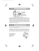
PRESIDENT LTD 260 User Manual Download Page 7

TRANSDUCER WETTING
Immediately before your vessel, thoroughly wipe the face of the transducer with a detergent type
liquid soap. This reduces the amount of time required for the transducer to establish good contact
with the water. If this procedure is not followed it may take several days for the complete “wetting”
to occur, resulting in reduced performance of the instrument.

There are a variety of transducers available for use on the many styles of boats available and the
preference of the boat owner. The three most popular styles are:

TRANSOM MOUNT: Ideal on boats with outboard engine or on I/O driven boats installed on
the stern of the boat)

THROUGH THE HULL: Installation is ideal for boats with Inboard engine(s)

INSIDE THE HULL: Often called Shoot Through Transducer can be used effectively if
procedures for installation are followed carefully.

“STYLE” OF THROUGH-THE-HULL TRANSDUCERS:
Transducer manufacturers build many different styles of transducers. The two most popular styles
of Through the Hull transducers are Low Profile types which typically are 1 3/4” or 2” in diameter
of Stem Type transducers which typically have a ¾” pipe thread and require a fairing block to level
it.

“MATERIAL” OF THROUGH-THE-HULL TRANSDUCERS:
The two most popular materials used are nylon and bronze.

WOODEN BOATS require the use of a bronze transducer or bronze fittings due to the fact
that when the boat is out of the water, the wood will dry out. When the fitting is installed and
the boat returned to the water, the wood will swell and possibly crack a nylon type of
transducer. Therefore, bronze is recommended for all wooden boat applications.

LARGER FIBERGLASS BOATS often prefer bronze transducers and fittings due to the size
of the boat and the total number of fittings used in the installation.

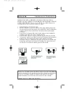
NYLON OR BRONZE - LOW PROFILE TRANSDUCERS
Ideal for high speed sport boats and sailboats, this style of transducer is designed to be mounted
flush against the hull without a fairing or leveling block. The hull deadrise angle must not exceed
15° in order to use this transducer fitting.

SAILBOATS: Normally a maximum beam amidships or in front of the keel.

POWERBOATS: Off centerline, 6”-12” and before the first lifting strake (flat area). Do not
install it on a lifting strake since this is the area where air bubbles travel from the bow to the
stern in order to provide a smooth ride.

INSTALLATION:

DEPTH TRANSDUCERS

7

LTD260.qxd  12/15/98  8:24 AM  Page 7

Summary of Contents for LTD 260

Page 1: ...LTD260 DIGITAL DEPTH LOG LTD260 qxd 12 15 98 8 24 AM Page 1...

Page 2: ...does not reduce the need for caution or judgment No electronic navigation system is absolutely reliable outputs may occasionally be incorrect The careful navigator should never rely solely on one devi...

Page 3: ...th a soft glowing lamp designed to help your night time navigational needs GENERAL OVERVIEW 3 FEATURES INSTALLATION WIRING 4 INSTALLATION LTD 260 4 GENERAL INFORMATION DEPTH SOUNDER TRANSDUCER 5 INSTA...

Page 4: ...f the dash panel Look at the front of the instrument to ensure that it is aligned properly and then tighten securely On the rear of the unit locate the terminal lugs extending out of the rear of the i...

Page 5: ...SE Because the unit consumes 25 amps of current when it is on you will want to keep your battery fully charged UNDERSTANDING SONAR All depth sounders emit Ultra Sonic Sound signals by a transducer int...

Page 6: ...e your instrument to not operate properly Removal of the identification tag will void the warranty SALTWATER MAINTENANCE ANTIFOULING PAINT Antifouling Paint If the vessel is kept in saltwater sea grow...

Page 7: ...typically have a pipe thread and require a fairing block to level it MATERIAL OF THROUGH THE HULL TRANSDUCERS The two most popular materials used are nylon and bronze WOODEN BOATS require the use of...

Page 8: ...able as far away as possible from engines motors and other wires 5 If you leave your boat in the water follow the instructions for transducer maintenance and or painting the face of the transducer wit...

Page 9: ...shielded from direct contact with the flow of water INSTALLATION LOW PROFILE TRANSDUCER Mount the transducer through the hull using the following steps 1 Drill an 1 8 pilot hole in the preferred trans...

Page 10: ...ERBOAT BRONZE STEM TYPE TRANSDUCER 1 Drill a 1 8 pilot hole in the preferred transducer location Reference previous section on determining the best location for your type of boat 2 Drill a hole slight...

Page 11: ...E HULL TRANSDUCER 1 Select a relatively thin area of the hull Avoid any built up areas that have been added to strengthen the hull 2 The transducer must be below the waterline and in an area where it...

Page 12: ...increments fro A03 through A10 feet ie 3 4 5 6 7 8 9 10 After A10 alarm setting are by two foot increments ie 10 12 14 16 18 20 feet The alarm setting jump by five foot increments ie A20 A25 A30 When...

Page 13: ...FITTINGS of wood may overstress the plastic housing Do not use bronze housings in aluminum hulls since electrolytic corrosion will occur TRANSDUCER All depth sounders emit ultrasonic sound signals th...

Page 14: ...r the instructions in this manual Inside the hull transducers must be properly bonded and attached to the hull as described in the section on inside the hull mounting or must be properly installed by...

Page 15: ...ly caused by a poor solder connection lack of solder or improper wiring HOW TO SOLVE Return the unit to the factory for repair The Shallow Water Sensitivity controls a circuit in the depth sounder tha...

Page 16: ...es much like the volume control on a radio If you turn it all the way down you cannot hear the music Turning it up too far makes the music blare and sound out of tune Turning the sensitivity control t...

Page 17: ...s Shallow Water Transducer Frequency 200 KHz Transducer Beam Angle Standard beam is 27 degrees Transmit Power 600 Watts Peak to Peak 70 Watts RMS Power Requirements 11 5 16 volts DC Draws 25 amps Max...

Page 18: ...el against loss or damage 2 Proof of Purchase date has been established by completing and returning the Warranty Registration Card to PRESIDENT within ten 10 days of the date of purchase A copy of the...

Page 19: ...use common sense regarding storage in extreme weather conditions Service performed by PRESIDENT for instruments Out of Warranty will be charged at a Fixed Rate established at the beginning of each ca...

Page 20: ...Worth TX 76155 Facsimile 817 858 3311 Telephone 817 858 3300 PRESIDENT Service Facilities 4700 Amon Carter Blvd Fort Worth TX 76155 Facsimile 800 323 2641 Telephone 800 586 0409 Part Number 103 014 1...

Reviews: