(3) - LED brightness factor
[Memories 200 & 201]
The red & blue LEDs can have their brightness individually set
1 = LEDs are at lowest brightness.
20 = LEDs are at full brightness.
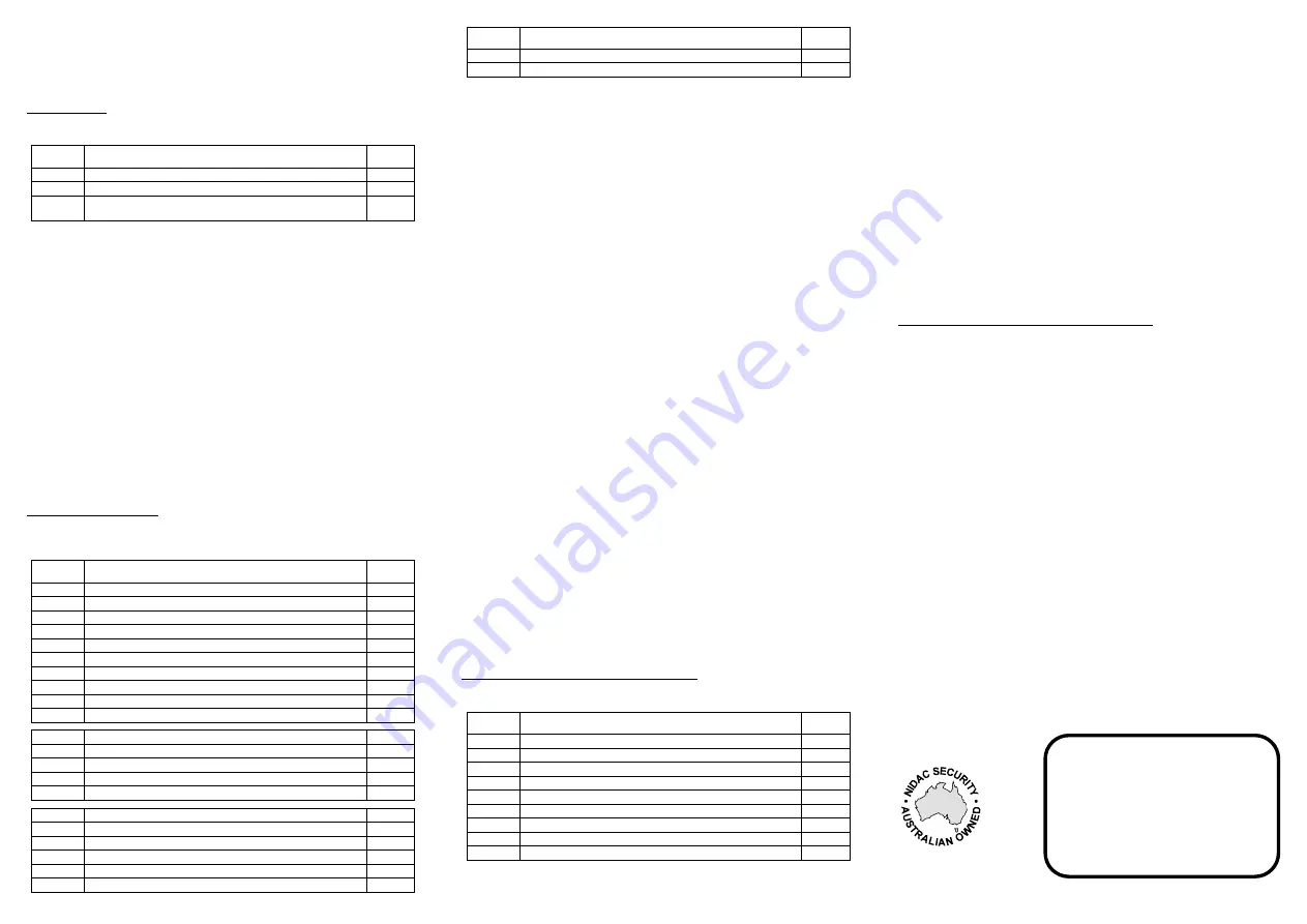
Presco Options
These options set how the PSC16 operates when in Presco mode. It is unlikely
that these options will need to be changed.
Memory
Number
Function
Default
Value
010
Internal/External mode Presco keypad
(4)
255
011
Process received DTA characters
(5)
255
012
Presco proximity reader output format (standard or KC compatible)
(6)
255
(4) - Internal/External mode Presco keypad
[Memory 010]
101 = Internal mode keypad.
All other values = External mode keypad.
Note:
When set to internal mode the two button Emergency (
) and One
Way Arm (
) features are enabled when used with a KC2 or KC6. This
setting has no effect when the unit is being used with any other Presco decoder
(e.g. PAC1 or PAC2).
(5) - Process received DTA characters
[Memory 011]
101 = Ignore all received DTA characters (PSC16 will not give beeps, warble, etc.
after final
is pressed).
All other values = PSC16 will make beeps, warble, etc. for DTA characters
received after pressing the final
key.
(6) - Presco proximity reader output format (standard PAC format or KC
compatible)
[Memory 012]
101 = Presco output from the prox reader is 7 digit KC compatible as per a PIM
wiegand to Presco conversion (only works for 26 bit wiegand cards).
202 = Presco output from the prox reader is 7 digit KC compatible using the
lowest 7 digits of the 9 digit Presco PAC code.
All other values = Presco output from RFID is standard 9 digit PAC format.
Wiegand Keypad Options
These options set the format of the wiegand data sent by the keypad when
wiegand mode is selected. The keypad can send up to 64 bits of data including
a site code up to 32 bits.
Memory
Number
Function
Default
Value
020
Site code byte 3
0
021
Site code byte 2
0
022
Site code byte 1
0
023
Site code byte 0 (used for standard 8 bit site code)
1
024
Number of bits in site code (0 to 32)
8
025
Number of bits in user code (8 to 64)
16
026
Number of bits for start parity calculation
(7)
12
027
Number of bits for end parity calculation
(7)
12
028
Parity polarity
(8)
2
029
Error handling
(9)
255
032
Wiegand burst mode
(10)
255
033
Custom wiegand total number of bits
(11)
255
034
Send LSB first
(12)
255
035
Site code start bit number
255
036
User code start bit number
255
040
Default custom wiegand pattern byte 7
(13)
255
041
Default custom wiegand pattern byte 6
(13)
255
042
Default custom wiegand pattern byte 5
(13)
255
043
Default custom wiegand pattern byte 4
(13)
255
044
Default custom wiegand pattern byte 3
(13)
255
045
Default custom wiegand pattern byte 2
(13)
255
Memory
Number
Function
Default
Value
046
Default custom wiegand pattern byte 1
(13)
255
047
Default custom wiegand pattern byte 0
(13)
255
(7) - Number of bits for parity calculation
[Memories 026, 027, 064 & 065]
Number of bits for parity calculation (0 = no parity bit, if the value is greater than
the total number of wiegand data bits (site code + user code bits) then it will use
half the total number of bits, for an odd number of bits the end parity will use 1
more bit).
(8) - Parity polarity
[Memories 028 & 066]
0 = Start parity is Even, End parity is Even.
1 = Start parity is Odd, End parity is Even.
2 = Start parity is Even, End parity is Odd (default value).
3 = Start parity is Odd, End parity is Odd.
(9) - Error handling
[Memory 029]
This memory specifies what information is sent via the wiegand interface when
a code entered is too large to be represented by the current wiegand format.
E.g. Standard 26 bit wiegand has a 16 bit user code which allows a maximum
code number of 65535. This memory determines what happens when a number
greater than 65535 is entered.
101 = A code of 0 is sent.
202 = No information is sent, the keypad ignores the input.
All other values = The maximum allowable code number for the current format
is sent (for 26 bit wiegand this is 65535).
(10) - Wiegand burst mode
[Memory 032]
101 = 4 bit burst mode,
,
&
keys data enabled (
=
).
121 = 4 bit burst mode,
,
&
keys data disabled.
202 = 8 bit burst mode,
,
&
keys data enabled (
=
).
212 = 8 bit burst mode,
,
&
keys data disabled.
All other values = Standard, non burst mode wiegand.
(11) - Custom wiegand total number of bits
[Memory 033]
When this memory is set to a value from 8 to 64 it overrides the standard wiegand
format of
start parity
followed by
site code
then
user code
then
end parity
and
replaces it with a fully customisable format with a total number of bits (including
any parity bits) as specified in this memory.
Note
that using this option requires a high understanding of wiegand data. Nidac
will only offer limited support for this feature.
(12) - Send LSB first
[Memory 034]
101 = LSB of data is sent first for both site and user code.
All other values = MSB of site and user code data sent first.
(13) - Default pattern bytes
[Memories 040 to 047]
When the custom wiegand format is used by setting memory 033 then the data
in these memories is used to define the value for those bits not in use by the site
code, user code and parity bits. The data used starts from Bit 0 (LSB) in Default
Pattern byte 0 (memory 047), e.g. if the total number of bits is set to 24 then
Default Pattern bytes 2, 1 & 0 are used.
Wiegand Em
Card Proximity Reader Options
These options set the format of the wiegand data sent by the PSC16 when it is
in wiegand mode and an Em
RFID card or tag is being read.
Memory
Number
Function
Default
Value
060
26 bit wiegand Em
card site code byte to use
(14)
255
061
Em
card custom wiegand format
(15)
255
062
Number of bits in Em
card site code
(16)
8
063
Number of bits in Em
card user code
(16)
16
064
Number of bits for Em
card start parity calculation
(7)
255
065
Number of bits for Em
card end parity calculation
(7)
255
066
Em
card parity polarity
(8)
2
067
Data start bit from Em
card for site code
(17)
1
068
Data start bit from Em
card for user code
(17)
25
(14) - 26 bit wiegand Em
card site code byte to use
[Memory 060]
101 = Use alternate site code byte 1 from Em
card.
202 = Use alternate site code byte 2 from Em
card.
All other values = Standard Presco reader site code byte used.
(15) - Em
card custom wiegand format
[Memory 061]
101 = 34 bit wiegand (16 bit site code, 16 bit user code, even start & odd end
parity bits for 16 data bits each) using Presco data.
121 = 34 bit wiegand as above using alternate site code data bytes.
202 = Custom wiegand format as defined by memories 62 to 68.
All other values = Standard 26 bit wiegand`.
(16) - Number of bits in Em
card site/ user code
[Memories 062 & 063]
A maximum of 40 data bits can be set as a sum of these 2 memories. If the sum
exceeds 40 then the number of site code bits will be automatically reduced.
(17) - Data start bit from Em
card
[Memories 067 & 068]
There are 40 bits of data in an Em
card organised as D00-D03, D10-D13, D20-
D23, D30-D33, D40-D43, D50-D53, D60-D63, D70-D73, D80-D83 and D90-D93.
Bit D00 is referred to as bit 1 for this memory and bit D93 as bit 40.
Be careful when setting the start bit to ensure that there are enough bits after the
start bit for the number of bits set for the site or user code data.
SETTING THE OPTIONS VIA THE PSC16 KEYPAD
To set any of the above options the PSC16 first needs to be placed into option
setting mode, this is done by following the steps below:
1. Remove power from the PSC16.
2. Connect the Orange wire to 0V
or
hold down the
key.
3. Reapply power.
4. Once the LED starts to double flash blue you are in option setting mode.
5. Disconnect the Orange wire or release the
key.
6. The PSC16 will remain in option setting mode for 5 minutes from the last
attempted option setting sequence.
Setting an option memory value
<3 digit memory number> <1 to 3 digit value>
.
Reset all option memories to factory defaults
whilst in option setting mode.
Exit Option Setting Mode
or wait 5 minutes after last option setting attempt.
NOTE:
Remember to disconnect the orange wire from 0V afterwards so that
should power go off the PSC16 will not start up in option setting mode when the
power is restored.
100%
NIDAC SECURITY PTY. LTD.
MANUFACTURERS OF SECURITY EQUIPMENT
A.B.N. 49 004 933 242
2 Cromwell Street
Burwood, Victoria
Australia 3125
t:
+61 3 9808 6244
e:


