background image

AFV-P  Series  High  Performance  Programmable  AC  Power  Supply 


24


3.3


MAIN Page 

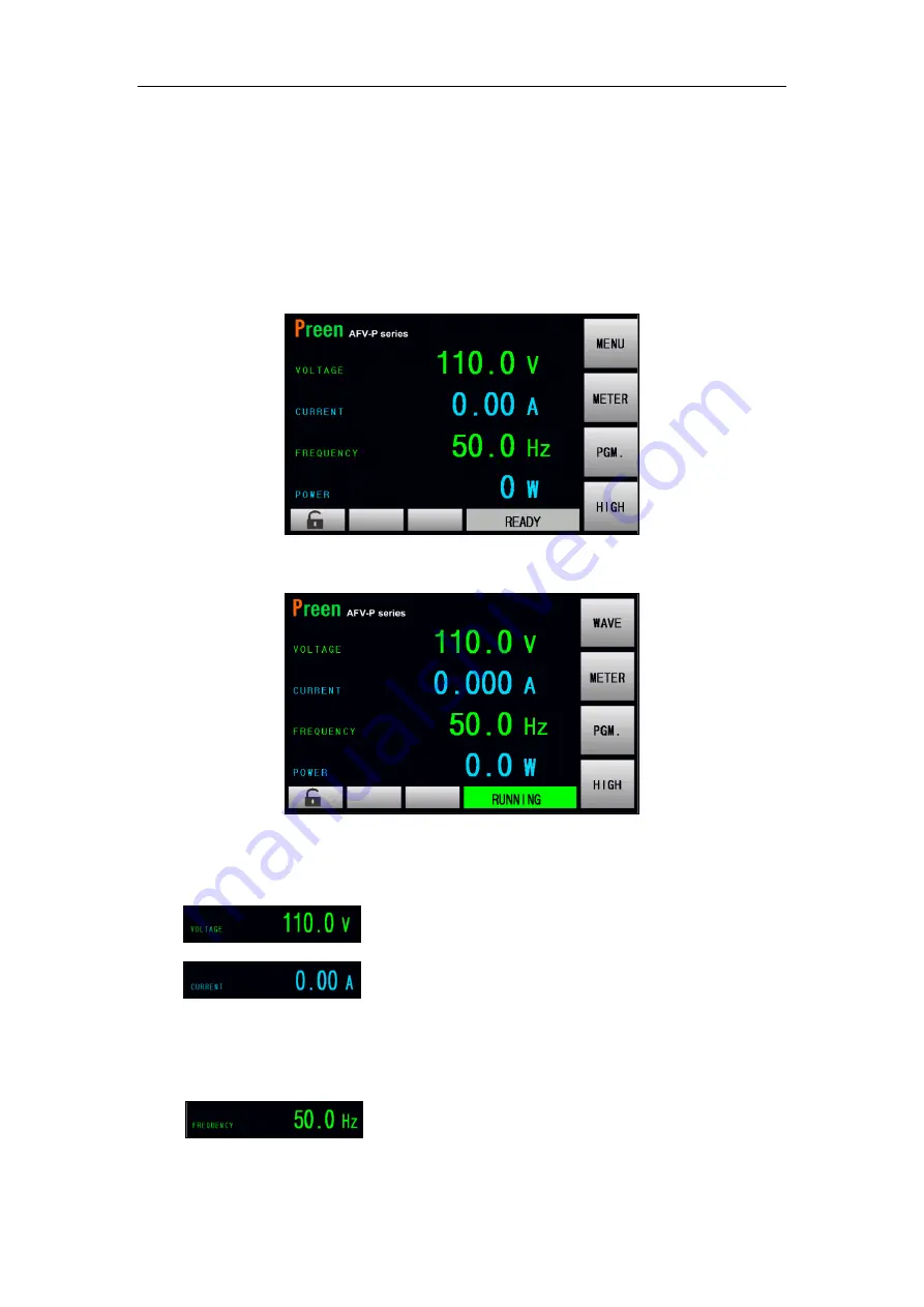
When users turn on the product, the  touch screen  shows the MAIN  page after the 
power-on procedures. The MAIN page shows the output settings and the measure-
ment readings of the product output. Users can set output value by using the touch 
screen or the rotary knob (refer to Subsection 3.2), and then press the output & reset 
button  on  the  front  panel  to  enable  the  output  of  the  product.  Please  see the  fol-
lowing figures: 


Figure 3.4 MAIN page when the product output is off 


Figure 3.5 MAIN page when the product output is on 


The description for the items and the icons on the MAIN page are given as follows: 

1)


  : Press to set the output voltage. 

2)


  : Press to set the maximum output current.


When the 

output current exceeds the set value of maximum output current, the prod-

uct will shut down the output. This set value of maximum output current can 

also applied to the OC-FOLD mode, refer to Subsection 3.5.2.2.   

3)


  : Press to set the output frequency. 

Summary of Contents for AFV-P Series

Page 1: ...P Series High Performance Programmable AC Power Supply User Manual AC Power Corp Preen V 1 08EN The information in this document is subject to change without notice AC Power Corp Preen All rights rese...

Page 2: ...s for a particular purpose AC Power Corp shall not be held liable for errors contained herein or direct indirect special incidental or consequential damages in connection with the furnishing performan...

Page 3: ...billed at cost Preen assumes no responsibility for its product being used in a hazardous or dan gerous manner either alone or in conjunction with other equipment High voltage used in some products may...

Page 4: ...efore turning on the power 3 NECESSITY OF PROTECTIVE GROUNDING Never cut off the internal or external protective grounding wire or disconnect the wiring of protective grounding terminal Doing so will...

Page 5: ...ion 12 2 4 1 Notices for DC output of AFV P Series 13 2 5 Remote Sense Connection 14 2 6 Power on Procedures 15 2 7 Product Handle Installation 16 2 8 Interface Card Installation 16 2 8 1 RS232 RS485...

Page 6: ...ptional 58 3 7 RESULTS Page 60 3 8 WAVE Page 61 3 9 METER Page 63 3 10 INFORMATION Page 65 3 11 Protection 66 4 BASIC MODE MEMORY FEATURE 68 4 1 Setting Page of MEMORY Feature 69 4 2 Output Page of ME...

Page 7: ...8 Output Socket Current Specialize for AFV P 5000 105 7 REMOTE OPERATION 107 7 1 General 107 7 2 Remote Control Software General Mode 108 7 3 Remote Control Software Program Mode 111 7 4 Remote Contro...

Page 8: ...n and rotary knob for setting the product output which provide an easy operation and measurement reading display Remote control for the product can be accomplished selectively via RS232 RS485 Ethernet...

Page 9: ...e control via RS232 RS485 Ethernet USB or GPIB 3 Protection for OVP LVP OCP OPP OTP RCP Fan Fail and AMP Fail 4 Temperature controlled fan speed B Input Output 1 Selective output voltage range with fu...

Page 10: ...V user selectable opt 0 320Vor 0 620V Voltage Resolution 0 1V Frequency A 15 1000Hz B 40 500Hz Frequency accuracy 0 2 Frequency Resolution 0 1Hz at 15 100Hz 1Hz at 100 1000Hz Max Current RMS 5A 2 5A 1...

Page 11: ...Power Resolution Hi 1W Lo 0 1W Hi 1W General Efficiency 77 at Max Power 80 at Max Power Protection OVP UVP OCP LVP OPP OTP RCP Fan Fail and AMP Fail Remote Interface Standard RS232 RS485 Ethernet USB...

Page 12: ...1 4 Exterior Product exterior of the AFV P series are given as follows a Front side view of the AFV P series b Right side view of the AFV P series Figure 1 3 Product exterior of the AFV P series Figur...

Page 13: ...or options by manipulating the touch screen to the desired one 3 Rotary Knob Input programming data or options by turning the rotary knob to the desired one 4 Output Reset Button Press this button to...

Page 14: ...Performance Programmable AC Power Supply 7 Figure 1 7 Rear panel for the product models of AFV P 1250 Figure 1 8 Rear panel for the product models of AFV P 2500 Figure 1 9 Rear panel for the product m...

Page 15: ...a the USB cable 9 RS232 RS485 Interface This interface is used for remote control via the RS232 RS485 cable 10 Ethernet Interface This interface is used for remote control via the Ethernet ca ble 11 I...

Page 16: ...please file a claim with the carrier immediately Do not return the product to the factory without obtaining the prior Return Merchandise Authori zation RMA acceptance from Preen 2 2 User Preparation B...

Page 17: ...tting too high and having bad impact on product life 3 The device should be located in proper ventilation the ambient temperature and humidity should not be high Stay away from liquid flammable gases...

Page 18: ...rminals of the product as follows 2 1 green or yellow wire to the terminal G of the input terminals 2 2 white or blue wire to the terminal N of the input terminals and 2 3 black or brown wire to the t...

Page 19: ...atch the safety requirements the safety cover for the output terminals must be fastened The wires to the load must be sufficiently large gauges so they will not overheat while carrying the output curr...

Page 20: ...serial first and then connect the high capacity capacitor in parallel Do not directly connect the high capacity capacitor in parallel Doing so could cause output unstable and trigger the product prot...

Page 21: ...o the corresponding ter minal of the load Because the sensing leads carry only a few millamperes the sens ing leads are much lighter than the load leads The sensing leads are part of the feedback path...

Page 22: ...se a potential shock hazard that could result in personal injury Apply power and press the power switch to turn on the product then the touch screen located on the front panel will light up and displa...

Page 23: ...roduct please refer to the Figure 2 8 to fix the handles to the product with eight screws Figure 2 8 Product handle 2 8 Interface Card Installation To install the interface card or replace the standar...

Page 24: ...232 RS485 9 Pin D Type female connector Pin NO Definition 1 No Connection 2 RS232 TX 3 RS232 RX 4 No Connection 5 GND 6 No Connection 7 RS485 D 8 RS485 D 9 No Connection 2 8 2 PLC Remote In Out Connec...

Page 25: ...and are shorted during activation The maximum permissible current is 1A 2 8 3 Analog Control Interface Card Optional Preen provides an optional analog control card AFV P 003 for remote control see the...

Page 26: ...ax 5 Voltage input mode 25mA max 5 Current input mode Analog Signal Output Output range 0 5Vdc or 0 10Vdc or 4 20mA select Accuracy 0 2 full scale Resolution 1 4200 max Digital Signal Input High volta...

Page 27: ...n 2 Pin5 GND Monitoring Pin 12 Pin15 GND Setting Voltage 0 5Vdc or 0 10Vdc Output frequency 40 500Hz Output frequency opt 15 1000Hz Pin 3 Pin5 GND Monitoring Pin 13 Pin15 GND Setting Current 4mAdc 20m...

Page 28: ...AFV P Series High Performance Programmable AC Power Supply 21...

Page 29: ...using the touch screen and rotary knob on the front panel for users Each display of the touch screen on the product represents an operational page Before describing each operational page the followin...

Page 30: ...he rotary knob on the front panel to move the cursor shown on the touch screen and press the rotary knob to choose the desired item After choosing the de sired item continue to turn the rotary knob to...

Page 31: ...n the front panel to enable the output of the product Please see the fol lowing figures Figure 3 4 MAIN page when the product output is off Figure 3 5 MAIN page when the product output is on The descr...

Page 32: ...ptions of HIGH and AUTO 9 Shown the status of the output or the error code 10 Press to lock unlock the operation of the touch screen and only allow pages to switch between the MAIN page and the METER...

Page 33: ...ange with two options of HIGH and AUTO Users can press the icon to set output voltage range at the MAIN page HIGH indicates that the maximum output voltage will be 310V AUTO indicates that the maximum...

Page 34: ...ENU page is given as follows 1 Press to enter into the SETTINGS page 2 Press to enter into the PROGRAMMABLE page 3 Press to enter into the COMMUNICATION page 4 Press to enter into the RESULTS page 5 P...

Page 35: ...two subpages the TESTING subpage and the SYSTEM subpage 3 5 1 TESTING Subpage ADVANCED Mode After pressing the icon to enter into the SETTINGS page the TESTING sub page at the ADVANCED mode will be sh...

Page 36: ...rt angle with options from 0 to 359 5 Press to set the end angle with options from 0 to 359 6 Press to set the power on status with three options of OFF ON and LAST 7 Press to set the voltmeter point...

Page 37: ...n be seen on the lower left side of the touch screen that is the icon Users can set the operational mode from the default ADVANCED mode to the BASIC mode by pressing the icon twice at the TESTING subp...

Page 38: ...fit their application Then the MAIN page will change correspondingly according to the output mode Figure 3 11 MAIN page when the output mode is AC Figure 3 12 MAIN page when the output mode is DC The...

Page 39: ...value of maximum output current the product can automatically control the output voltage to maintain the output current at the up limit For the principle of operation refer to Subsection 3 5 2 2 The p...

Page 40: ...rotary knob refer to Subsection 3 2 In other words the product can control the output phase angle that is the start angle and the end angle of the output waveform Firstly the procedures of setting the...

Page 41: ...ly the procedures of setting the end angle from 0 to 270 by using the virtual numeric keys are given as below 1 Press the item to use the virtual numeric keys to set the value of 270 2 Press the icon...

Page 42: ...he output is on after turning on the product LAST indicates that if the output remains on while turning off the product previously the output is on after turning on the product currently otherwise the...

Page 43: ...signal EVENT OFF and ON and the default option is EVENT EVENT indicates that the product outputs a 5V DC pulse signal when the product output changes OFF indicates that the synchro nized signal is dis...

Page 44: ...oint is located at the terminals SN and SL of the output terminals The procedures of setting the voltmeter point from INT to EXT are given as below 1 Press the item twice to switch the icon status fro...

Page 45: ...nd ON and the default option is OFF OFF indicates that the product will continue the output when the measurement readings exceed the values ON indicates that the product will stop the output when the...

Page 46: ...when the PROGRAMMABLE feature is performed OFF indicates that the HINT page will be displayed between each Step of the Memory Set for users to confirm when the PROGRAMMABLE feature is performed The pr...

Page 47: ...erational mode can be referred to Section 3 5 1 Please see the following figures Figure 3 24 TESTING subpages 1 2 BASIC mode Figure 3 25 TESTING subpages 3 4 BASIC mode The description for the items a...

Page 48: ...maximum output voltage with options from 0V to 310V 9 Press to set the minimum output voltage with options from 0V to 310V 10 Press to enable disable the synchronized signal with three options of EVE...

Page 49: ...he TESTING subpage 1 BASIC mode to fit the product application Then the MAIN page will change correspondingly according to the output mode see Fig ure 3 26 The procedures of setting the output mode fr...

Page 50: ...fer to Subsection 3 3 The response time starting from the output current exceeding the up limit till fall ing back to the up limit is 1 4S In practical applications it can effectively improve the star...

Page 51: ...he output waveform Firstly the procedures of setting the start angle from 0 to 90 by using the virtual numeric keys are given as below 1 Press the item to use the virtual numeric keys to set the value...

Page 52: ...e output is on after turning on the prod uct LAST indicates that if the output remains on while turning off the product previ ously the output is on after turning on the product currently otherwise th...

Page 53: ...15Hz to 1000Hz by us ing the touch screen and the rotary knob refer to Subsection 3 2 When users set value of the output frequency exceeding the preset range that is the preset value of maximum to mi...

Page 54: ...the product EXT indicates that the voltmeter point is located at the terminals SN and SL of the output terminals The procedures of setting the voltmeter point from INT to EXT are given as below 1 Pres...

Page 55: ...e SYSTEM subpage Please see the following figures Figure 3 34 SYSTEM subpages 1 2 Figure 3 35 SYSTEM subpage 3 The description for the items and the icons at the SYSTEM subpage are given as follows 1...

Page 56: ...the next page of the SYSTEM subpage 3 5 3 1 Operational Language At the SYSTEM subpage 1 users are allowed to set the operational language with four options of ENGLISH and and the default operational...

Page 57: ...uch screen and the rotary knob refer to Subsection 3 2 and the default alarm volume is 5 The bigger the number is the higher the alarm volume is The procedures of setting the alarm volume from 5 to 9...

Page 58: ...g the touch screen and the rotary knob refer to Subsection 3 2 and the default backlight level is 9 The bigger the number is the brighter the touch screen is The procedures of setting the backlight le...

Page 59: ...nly display the result of the last Step Loop at the RESULTS page after performing the PROGRAMMABLE feature ALL indicates that the product will display each Step Loop at the RESULTS page after performi...

Page 60: ...n as below 1 Press the item twice to switch the icon status from OFF to ON 2 Press the icon to confirm and lock the PROGRAMMABLE feature Figure 3 40 Lock the PROGRAMMABLE feature B Reset to the Defaul...

Page 61: ...NET Subpage After pressing the icon to enter into the COMMUNICATION page the ETHERNET subpage will be shown on the touch screen in advance Please see the following figures Figure 3 42 ETHERNET subpage...

Page 62: ...C Power Supply 55 5 Press to set the MAC address under the MANUAL mode 6 Press to set the Ethernet port under the MANUAL mode 7 Press to move to the previous page of the ETHERNET subpage 8 Press to mo...

Page 63: ...e following figures Figure 3 43 GENERAL subpages 1 2 The description for the items and the icons at the GENERAL subpage are given as fol lows 1 Press to enable disable the PLC remote feature 2 Press t...

Page 64: ...B interface card re fer to Subsection 2 8 the GENERAL subpage with the GPIB interface will be shown on the touch screen Please see the following figure Figure 3 44 GENERAL subpage with the GPIB interf...

Page 65: ...subpage will show on the screen in advance Please see the following figures Figure 3 45 ANALOG subpage The descriptions for the item and icons at the ANALOG subpage are given as follows 1 Press to ena...

Page 66: ...ed the voltage setting on the MAIN page will be 0 0V when there is no external signal inputs from the analog con trol card and an icon will show on the bottom left of the MAIN page indicating the remo...

Page 67: ...ESULTS page The description for the icons at the RESULTS page are given as follows 1 Press to see the settings of the desired Step of the Memory Set 2 Show the label number of the current Memory Set 3...

Page 68: ...into the WAVE page Please see the following figures Figure 3 49 WAVE page when the product output is off Figure 3 50 WAVE page when the product output is on Additionally when the product output is on...

Page 69: ...Press to set the display scale of the output current with two op tions of 2A and 20A per division for the product models of AFV P 600 and AFV P 1250 4A and 40A per division for the product model of AF...

Page 70: ...con to enter into the METER page Please see the following figures Figure 3 52 METER page when the product output is on Figure 3 53 METER page when the PROGRAMMABLE feature is performed Additionally wh...

Page 71: ...ng of the output fre quency 4 Show the measurement reading of the apparent power 5 Show the measurement reading of the power factor 6 Show the measurement reading of the peak current 7 Show the measur...

Page 72: ...TION page The description for the items at the INFORMATION page are given as follows 1 Show the producer of the product 2 Show the product model 3 Show the serial number of the product 4 Show the firm...

Page 73: ...le Cause Possible Solution OVP Over Voltage Protection 1 Load oscillation 2 Problem of the voltage feedbacking from the load to the inverter circuitries 3 Fault of the inverter con trol circuitries 1...

Page 74: ...Current Protection Problems of the current feedbacking from the load to the inverter circuitries Remove the load to inspect the output voltage Fan Fail Fan Failure Fault of the fan Seek the technical...

Page 75: ...sets If the MENU page is shown on the touch screen user can press the icon to enter into the MEMORY page Please see the following figure Figure 4 1 MEMORY page The description for the items and the ic...

Page 76: ...EMORY feature The description for the items and the icons at the MEMORY setting subpage are giv en as follows 1 Press to set the name of Memory Set within 10 characters including capital or lowercase...

Page 77: ...ges are listed by default for quick access Please see the following figure Figure 4 5 Frequency setting of Memory set 4 Press to enter into the subpage for advanced setting of Memory Set Please see th...

Page 78: ...el according to the set voltage HIGH The maximum output voltage to be 310V high level The maximum output current will be half of the low level in AUTO range B Press to set the maximum output current S...

Page 79: ...as follows 1 These are the fixed shortcuts to the first three Memory Sets Users can set the most commonly used voltages and frequencies in these three sets for quick switching 2 The forth shortcut is...

Page 80: ...s the output display of the MEMORY set in operation 5 Press to lock unlock the operation of the touch screen When the operation of the touch screen is locked only switching pages between the MAIN page...

Page 81: ...he STEP feature refer to Subsection 5 2 or make the output change according to the setting slew rate via the RAMP feature refer to Subsection 5 3 even make the output change according to the setting v...

Page 82: ...t the start number of the Memory Loop with options from 1 to 50 2 Press to set the end number of the Memory Loop with options from 1 to 50 3 Press to set the Memory Loop times with options from 1 to 9...

Page 83: ...y Set 2 to the Memory Set 6 and repeated 5 times The procedures of setting the Memory Loop according to the example mentioned above are given as below 1 Press the icon to enable the Memory Loop 2 Pres...

Page 84: ...output change step by step at the STEP page and 24 STEPs for each Memory Set are supported To enter into the STEP page of the desired Memory Set users can press the icon of the desired Memory Set Figu...

Page 85: ...set the Step Loop times with options from 1 to 999 4 Press to enter into the subpage of the desired Step 5 Show the label number of the current Memory Set 6 Press to enable disable the desired Step 7...

Page 86: ...f set the Step Loop according to the example mentioned above are given as below 1 Press the icon to set the value of 3 and press the icon to confirm 2 Press the icon to set the value of 7 and press th...

Page 87: ...trate the STEP feature the figures shown below are the example of setting the STEP feature for the Step 1 2 3 and the output waveform corresponding to this example Figure 5 9 Example of setting the ST...

Page 88: ...ubpage These subpages include the GENERAL subpage RAMP subpage and LIMITS subpage and the GENERAL subpage will be shown on the touch screen in advance after pressing the icon Please see the following...

Page 89: ...on 5 3 6 Press to enter into the LIMITS subpage 7 Press to move to the previous page of the GENERAL subpage 8 Press to move to the next page of GENERAL subpage D RAMP Subpage After pressing the icon a...

Page 90: ...subpage will be shown on the touch screen in advance Then users can press the icon to enter into the LIMITS subpage and enable the LIMITS feature to perform the out put test for the desired Step Pleas...

Page 91: ...0 from 0 01A to 20A for the product model of AFV P 2500 from 0 01A to 40A for the product model of AFV P 5000 While setting the maximum output current less than 0 01A the output test of the maximum ou...

Page 92: ...mum output power factor will be disabled and this icon status will be OFF 9 Press to set the minimum output power factor for the desired Step with options which are similar to that of the maximum outp...

Page 93: ...he maximum output crest factor less than 0 01 the output test of the maximum output crest factor will be disabled and this icon status will be OFF 15 Press to set the minimum output crest factor for t...

Page 94: ...99 While setting the Ramp time per unit less than a default value for Ramp time unit SECOND and CYCLE this constant value is 1 for Ramp time unit MILLISECOND this constant value is 10 the setting of t...

Page 95: ...next page of RAMP subpage B RAMP Feature Example To illustrate the RAMP feature the figures shown below are the example of setting the RAMP feature for the Step 1 and the output waveform corresponding...

Page 96: ...fic period of time at the TRANSIENT page Please see the following figures Figure 5 21 Enter into the TRANSIENT page Figure 5 22 TRANSIENT page 1 2 The description for the items at the TRANSIENT page a...

Page 97: ...performed every cycle once 6 Press to move to the previous page of the TRANSIENT page 7 Press to move to the next page of TRANSIENT page B TRANSIENT Feature Example To illustrate the TRANSIENT featur...

Page 98: ...AFV P Series High Performance Programmable AC Power Supply 91 Figure 5 25 Output waveform corresponding to the example above...

Page 99: ...n AFV P series provides TRIAC simulation to simulate the phase an gle change of output voltage between 0 180 which can meet the requirement of Design Verification Testing and Automatic Production Test...

Page 100: ...function 2 Press to select LEADING EDGE DIMMING or TRAILING EDGE DIMMING 3 Press to set dimming angle from 0 to 180 4 Press to set the dimming cycle with options from 1 to 9999 5 Press to move to the...

Page 101: ...a current meter and suita ble load are needed while performing the calibration procedures Connections for the instruments mentioned above please refer to the figure below Figure 6 1 Instrument connec...

Page 102: ...given as follows 1 Press to enter into the page which calibrates the HI Range voltage 310V 2 Press to enter into the page which calibrates the LO Range voltage 155V 3 Press to enter into the page whic...

Page 103: ...nge RMS current 7 Press to enter into the page which calibrates the peak current 8 Press to enter into the page which calibrate the output socket current specialize for the product model of AFV P 5000...

Page 104: ...panel to enable the calibration of the HI Range voltage 310V refer to Figure 6 6 and then the product will start to output the voltage which is closed to 310V 4 Use the rotary knob to adjust the prod...

Page 105: ...panel to enable the calibration of the LO Range voltage 155V refer to Figure 4 8 and then the product will start to output the voltage which is closed to 155V 4 Use the rotary knob to adjust the prod...

Page 106: ...panel to enable the calibration of the HI Range voltage 60V refer to Figure 6 10 and then the product will start to output the voltage which is closed to 60V 4 Use the rotary knob to adjust the produc...

Page 107: ...panel to enable the calibration of the LO Range voltage 60V refer to Figure 6 12 and then the product will start to output the voltage which is closed to 60V 4 Use the rotary knob to adjust the produ...

Page 108: ...calibration of the HI Range RMS current refer to Figure 6 14 and then the product will start to output the voltage which is closed to 100V 4 Use the rotary knob to adjust the product output until the...

Page 109: ...6 1 3 Press the output reset button on the front panel to enable the calibration of the LO Range RMS current refer to Figure 6 16 and then the product will start to output the voltage which is closed...

Page 110: ...to enter into the page which calibrates the peak current refer to Figure 6 17 2 Connect the product with the current meter and suitable load refer to Figure 6 1 3 Press the output reset button on the...

Page 111: ...ng the peak current are given as follows and the suitable load shall be resistive load Model Resistive Value Rated Power AFV P 600 20 500W AFV P 1250 10 1000W AFV P 2500 5 2000W AFV P 5000 2 5 4000W F...

Page 112: ...instruments mentioned above please refer to the figure below Figure 6 199 Instrument connection for calibration The procedures of calibrating the output socket current are given as below 1 Press the i...

Page 113: ...FV P Series High Performance Programmable AC Power Supply 106 Figure 6 20 Enter into the page which calibrates the output socket current Figure 6 21 Enable the calibration of the output socket current...

Page 114: ...fer to the file READ ME to find the SCPI program ming manual 7 1 General With the complete communication interfaces the product can be controlled re motely via RS232 RS485 or USB Additionally the prod...

Page 115: ...follows 1 Use to set the output voltage 2 Use to set the output frequency 3 Use to set the rated current 4 Use to set the rated power 5 Click to set the output voltage range 6 Click to enable the pro...

Page 116: ...The description for the items at the setting page of the remote control software is similar to the description for the SETTINGS page mentioned ac cording to Subsection 3 5 15 Click to exit the remote...

Page 117: ...AFV P Series High Performance Programmable AC Power Supply 110 Figure 7 6 Setting page of the remote control software...

Page 118: ...ntrol Software Program Mode To enter into the program mode of the remote control software please click the icon Program Mode which is mark in red square below Figure 7 7 Click the icon Program Mode to...

Page 119: ...n for the items at the PROGRAMMABLE page of the control software is similar to the PROGRAMMABLE page mentioned according to Chapter 5 2 Click to enable disable the Memory Loop 3 Use to set the start n...

Page 120: ...Load Default see Figure 7 11 2 Select the desired settings to reset 2 1 Clicktheicon Default SystemData to enable disable the reset ofthe system data 2 2 Click the icon Default AC Setting Date to enab...

Page 121: ...ures step by step 1 Click the item Test Report and then click the item Customize Report see Figure 7 13 2 Select the desired items to show on the product output report see Figure 7 14 3 Click the icon...

Page 122: ...Power Supply 115 8 Theory of Operation The product mainly consists of 8 function blocks and each of the function blocks has its own specific function The function blocks of the product are given as b...

Page 123: ...ety summary and read the manual carefully 2 Ensure the power line input is cut off and the device has been shut down for 20 minutes before maintenance 3 Clean the device regularly especially the air i...

Reviews: