background image

PRECISION DIGITAL CORPORATION 

89 October Hill Road • Holliston MA 01746 USA 
Tel (800) 343-1001 • Fax (508) 655-8990


www.predig.com 

P

RO

V

U

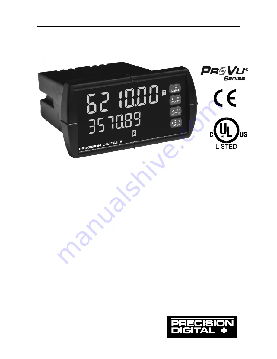
 Batch Controllers 

PD6210 Analog Input & 

PD6310 Pulse Input  


  PD6210: 0-20 mA, 4-20 mA, 0-5 V, 1-5 V, 

10 V Inputs 

  PD6310: Pulse, Open Collector, NPN, PNP, TTL, Switch 

     Contact, Sine Wave (Coil), Square Wave Inputs 

  NEMA 4X, IP65 Front 

  Start/Pause/Stop, Change Batch with Front Panel Buttons 

  Single or Multi-Stage Batch Control (Up to 8 Relays) 

 Automatic 

Overrun 

Correction 

  Rate in Units per Second, Minute, Hour, or Day 

  Automatic or Manual Batch Control 

  Low or High Flow Alarms 

  9 Digit Grand Total with Overflow Feature 

  Count Up or Down with Each Batch 

 Free 

MeterView

®

 Pro Software for Operation, Monitoring,  

     and Programming

Summary of Contents for PROVU PD6210

Page 1: ...NPN PNP TTL Switch Contact Sine Wave Coil Square Wave Inputs NEMA 4X IP65 Front Start Pause Stop Change Batch with Front Panel Buttons Single or Multi Stage Batch Control Up to 8 Relays Automatic Over...

Page 2: ...sonal injury or property loss Anyone using this product for such applications does so at his her own risk Precision Digital Corporation shall not be held liable for damages resulting from such imprope...

Page 3: ...8 Unpacking 18 Panel Mounting Instructions 18 Configuration for 12 or 24 VDC Power Option 20 Transmitter Supply Voltage Selection P P 21 Connections 21 Connectors Labeling 22 Power Connections 22 PD62...

Page 4: ...Action 55 Setting Batch Control Relays 55 Programming Alarm Set and Reset Points 56 Setting Fail Safe Operation 56 Programming Time Delay 56 Relay Action for Loss of 4 20 mA Input Loop Break 56 Relay...

Page 5: ...int Calibration Scaling 74 MeterView Pro Software 74 Noise Filter Bypass bypass 76 Modbus RTU Serial Communications serial 77 Select Menu SElEct 78 Signal Conditioning Selection Functn 78 Analog Outpu...

Page 6: ...ter Powered by Ext Supply or Self Powered 23 Figure 10 Voltage Input Connections 24 Figure 11 Flowmeter Powered by Internal Power Supply 25 Figure 12 Flowmeter Powered by External Supply 25 Figure 13...

Page 7: ...ossible Overrun correction adjusts the closing of the batch control relays to adjust for inaccuracies from batch to batch This increases accuracy over time as systems wear out At least two SPDT relays...

Page 8: ...D1104 PD6310 6H5 PD6310 7H5 2 relays 4 20 mA output PD1105 PD6310 6H7 PD6310 7H7 4 relays 4 20 mA output PD1107 Model number for replacement option card Accessories Model Description PDA1002 DIN rail...

Page 9: ...min or a Modbus display register Any rate display may be programmed to alternate with a custom unit or tag ALTERNATING DISPLAY Displays alternate every 10 seconds when display is se lected or the bat...

Page 10: ...als P P 24 VDC 5 200 mA max standard 12 24 VDC powered models rated 100 mA max 5 or 10 VDC 50 mA max selectable with internal jumper J4 NORMAL MODE REJECTION Greater than 60 dB at 50 60 Hz ISOLATION 4...

Page 11: ...d ddd d dd d d or dddddd CALIBRATION RANGE Input Range Minimum Span Input 1 Input 2 4 20 mA 0 15 mA 10 V 0 10 V An Error message will appear if the input 1 and input 2 signals are too close together I...

Page 12: ...ywhere above or below input 1 setting Minimum input span between any two inputs is 10 Hz An Error message will appear if the input 1 and input 2 signals are too close together FILTER Programmable cont...

Page 13: ...osure on digital inputs automatically via user selectable preset value and time delay or through serial communications GRAND TOTAL RESET PASS WORD Grand total passwords may be entered to prevent reset...

Page 14: ...and independent for each relay Note Relay coil is energized in non alarm condition In case of power failure relay will go to alarm state ALARM AUTO INITIALIZATION When power is applied to the controll...

Page 15: ...ts BYTE TO BYTE TIMEOUT 0 01 2 54 second TURN AROUND DELAY Less than 2 ms fixed Note Refer to the PROVU Modbus Register Tables located at www predig com for details PDA1044 Digital Input Output Expans...

Page 16: ...issions Class A AC Mains Conducted Emissions Class A IMMUNITY EN 61326 1 2006 Measurement control and laboratory equipment EN 61000 6 2 2005 EMC heavy industrial generic immunity standard RFI Amplitud...

Page 17: ...lations designed to optimize EMC performance All hardware is identical to the PD6210 and PD6310 controllers Declaration of Conformity available at www predig com SAFETY INFORMATION CAUTION Read comple...

Page 18: ...2 mm behind the panel for wiring Panel thickness 0 04 0 25 1 0 mm 6 4 mm Recommended minimum panel thickness to maintain Type 4X rating 0 06 1 5 mm steel panel 0 16 4 1 mm plastic panel Remove the two...

Page 19: ...Controllers Instruction Manual 19 Mounting Dimensions 1 76 45 mm 0 59 15 mm 4 77 121 mm 2 45 62 mm 5 05 128 mm Figure 2 Controller Dimensions Side View 3 61 92 mm 4 17 106 mm 4 68 119 mm Figure 3 Cont...

Page 20: ...ption are shipped from the factory ready to operate from 24 VDC To configure the controller for 12 VDC power 1 Remove all the connectors 2 Unscrew the back cover 3 Slide the back cover about 1 inch 4...

Page 21: ...he back cover about 1 inch 4 Configure the J4 jumper located behind the input signal connector for the desired excitation voltage as shown MAIN BOARD INPUT SIGNAL J4 5 V 10 V 24 V J4 CONFIGURATION Fac...

Page 22: ...he equipment and the controller DW1815 R I I MA OUT 1 3 2 POWER SIGNAL P COM P V mA 3 4 1 2 5 M LINK C NO NO NC NC C RELAY4 RELAY3 4 3 6 5 2 1 C NO NO NC NC C RELAY2 RELAY1 4 3 6 5 2 1 1 2 3 4 5 6 7 8...

Page 23: ...tions There are no switches or jumpers to set up for current and voltage inputs Setup and programming is performed through the front panel buttons mA P 2 1 3 5 4 P V COM INPUT SIGNAL 3 Wire 4 20 mA Tr...

Page 24: ...he nature of the overload The fuse limits the current to a safe level when it detects a fault condi tion and automatically resets itself when the fault condition is removed Voltage Signal mA P 2 1 3 5...

Page 25: ...p and programming is performed through the front panel buttons Flowmeter Pulse Output S P 2 1 3 5 4 P S COM INPUT SIGNAL V PNP NPN mV LEVEL TYPE Figure 11 Flowmeter Powered by Internal Power Supply S...

Page 26: ...SENSOR 4 7 k ohm Internal pull down Figure 12 PNP Sensor Powered by Internal Supply S P 2 1 3 5 4 P S COM INPUT SIGNAL V PNP NPN mV LEVEL TYPE SWITCH INPUT 4 7 k ohm Internal pull up 5 V Figure 13 Sw...

Page 27: ...e COM common terminal of the INPUT SIGNAL connector C NO NO NC NC C RELAY4 RELAY3 4 3 6 5 2 1 C NO NO NC NC C RELAY2 RELAY1 4 3 6 5 2 1 Figure 14 Relay Connections Switching Inductive Loads The use of...

Page 28: ...Connections Connections for the 4 20 mA transmitter output are made to the connec tor terminals labeled MA OUT The 4 20 mA output may be powered internally or from an external power supply 12 35 VDC...

Page 29: ...y are used to connect additional modules to the system Note The jumper located between the RJ45 connectors of the PDA1044 must be removed on the second digital I O module in order for the system to re...

Page 30: ...tact s are wired to digital input s and trigger the interlock relay This feature is enabled by configuring the relay and relative digital input s see page 59 In one example dry interlock contacts are...

Page 31: ...ds Overview There are no jumpers on the PD6210 to set for the controller input selec tion There are two switches on the PD6310 located to the right of the input connector which must be configured acco...

Page 32: ...installed Total overflow indicator M Manual control relays or analog output Programming Press the Menu button to enter or exit the Programming Mode at any time Press the Right arrow button to move to...

Page 33: ...al expansion module which are used to either control the batch process in single or multi stage batch control or as alarms that will be active when the batch process is running A 4 20 mA output option...

Page 34: ...s Total Press Enter to access preclose selection for multi stage control Precls Yes Yes to enable a preclose value for relay 2 Yes 00005 0 Set the preclose value to 5 for c closing the valve controlli...

Page 35: ...quals the preset relay 1 deactivates closing valve 1 Filling stops 5 The BATCH button is pressed and a new preset is entered 100 gallons and the enter STOP button is pressed to confirm it 6 The new ba...

Page 36: ...Model PD6210 PD6310 Batch Controllers Instruction Manual 36 36 36...

Page 37: ...to reset grand total Rst bc Reset batch count Press Enter to reset batch count Contrl Control Enter Control menu Auto Automatic Press Enter to set controller for automatic operation mAn Manual Press...

Page 38: ...GT tb Grand total time base Program grand total time base GT CF Grand total conversion factor Program grand total conversion factor GT rst Grand total reset Program grand total reset mode auto or man...

Page 39: ...e or GT OFF Off Disable relay and front panel status LED Select Off to enable Interlock feature Set 1 Set 1 Program set point 1 RSt 1 Reset 1 Program reset point 1 RLY 2 Relay 2 Relays 2 8 setup Note...

Page 40: ...Set or enter Password 2 Pass 3 Password 3 Set or enter Password 3 Total Total password Set or enter password for manual reset Gtotal Grand total password Set or enter password for manual reset nonrst...

Page 41: ...n when a batch is not running to enter Program ming Mode then press the Up arrow button to scroll main menu Press Menu at any time to exit and return to Run Mode Changes made to settings prior to pres...

Page 42: ...total grand totals batch count maximum or minimum reading peak or valley reached by the process both may be reset at the same time by selecting reset high low rst HL Control Menu Contrl The Control m...

Page 43: ...oller will accept 2 Enable or disable totalizer and batching features 3 Decimal point position 4 Program menu for scaling or calibration 5 Display parameter and intensity 6 Relay operation 7 4 20 mA a...

Page 44: ...ale menu to enter the scaling without a signal source Use the Calibrate menu to apply a signal from a calibrator or a flowmeter for the scaling Note The Scale and Calibrate functions are exclusive of...

Page 45: ...ller may be calibrated using the K Factor function Most flow meter manufacturers provide this information with the device Enter the K Factor Factor menu and select the decimal point with highest reso...

Page 46: ...tan dards Use the K Factor menu to match the rate totalizer with a flowmeter s k factor pulse unit of measure Or use the Scale menu to scale the pulse input pulse sec without a signal source Or use Ca...

Page 47: ...scaling process was not successful After the error message is displayed the controller reverts to input 2 during calibration or scaling and to input 1 during internal calibration allowing the appropri...

Page 48: ...ation as described on page 33 In automatic mode the batch process will auto matically begin after a completed batch The time delay for the restart may be 0 1 to 999 9 seconds t dly Automatic batch sta...

Page 49: ...s variable in engi neering units by applying the appropriate input signal and following the calibration procedure The use of a calibrated signal source is strongly recommended to cali brate the contro...

Page 50: ...can be programmed to display 1 Rate value 2 Total or grand total 3 Relay set points 4 Max min values 5 Engineering units or custom legends 6 Modbus input 7 Off no display 8 Display rate and units Disp...

Page 51: ...splay Setup Menu After setting up the input and the display press the Menu button to exit programming and skip the rest of the setup menu Press the Menu but ton again and the Up arrow to reach the Pro...

Page 52: ...cter Display Character 0 0 k K 1 1 l L 2 2 m m 3 3 n n 4 4 O O 5 5 o o 6 6 p P 7 7 q q 8 8 r r 9 9 s S A A t t b b u u C C v V c c u w w d d x X e E y Y f F z Z g G 9 g H H h h I I i i Space j J Degre...

Page 53: ...ar manual reset when not in a batch process only after alarm condition has cleared e Pump alternation control automatic reset only for level applications unrelated to batch control f Sampling the rela...

Page 54: ...f relay on Fls 1 off Fls 1 Fls 1 Failsf break relay ignore break1 On break1 break1 break Off break1 off dly 1 relay setup Act 1 rly 1 rst 1 rly 1 Asign1 Assign Asign8 Assign Relay Assignment Assign Th...

Page 55: ...t when not in a batch process non latching 5 Latching manual reset only when not in a batch process 6 Latching with Clear manual reset only when not in a batch process after alarm condition has cleare...

Page 56: ...condition exists The fail safe operation is set independently for each relay Select on to enable or select off to disable fail safe operation Programming Time Delay The On and Off time delays may be p...

Page 57: ...be set for sampling where the relay will activate for a specific amount of time after a certain grand total has been reached ie 2 second sample relay activation every 100 gallons batched There are thr...

Page 58: ...with manual reset are not recommended when using this controller for batch control as the manual reset will not be acknowledged during a batch process when the rate alarms are active For information...

Page 59: ...On 1 dI 1 dI 1 user 3 Connect a switch or dry contact between the 5V terminal and the corresponding digital input dI 1 to dI 4 terminal 1 2 3 4 5 6 5 I1 I2 I3 I4 O1 7 8 O2 O3 9 10 O4 G DI 1 4 DO 1 4 5...

Page 60: ...0 seconds every time the process has batched the amount pro grammed for the set point and every time this amount has been batched afterward See the diagram below for more details The utility of this...

Page 61: ...ergized in non alarm condition In case of power failure relay will go to alarm state Low Alarm with Fail Safe Operation Set Reset Reset Set Input Relay LED Automatic non latching de energized energize...

Page 62: ...d going up for high alarms and going down for low alarms The sample time can be programmed between 0 1 and 600 0 seconds Total Relay Sampling Operation When the batch total reaches the set point the r...

Page 63: ...alarm relay Relay LED Input Loop Break Ignore de energized energized off on Relay LED Loop Break Off Relay LED Loop Break On Set Reset When the controller detects a break in the 4 20 mA loop the rela...

Page 64: ...D When the signal crosses the set point the On time delay timer starts and the relay trips when the time delay has elapsed If the signal drops below the set point high alarm before the time delay has...

Page 65: ...o equipment is needed to scale the analog output simply program the display values to the corresponding mA output signal The Analog Output menu is used to program the 4 20 mA output based on display v...

Page 66: ...inputs Total Password Prevents resetting the total manually Gtotal Password Prevents resetting the grand total manually Protecting or Locking the Controller Enter the Password menu and program a six d...

Page 67: ...Caution Once the Grand Total has been programmed as non resettable the feature cannot be disabled Making Changes to a Password Protected Controller If the controller is password protected the controll...

Page 68: ...Password If the correct six digit password is entered the controller displays the message unLoc unlocked and the protection is disabled until a new password is programmed If the password entered is in...

Page 69: ...ons should only be used by users who are sure of their need in their application Advanced Features Menu To simplify the setup process functions not needed for most applications are located in the Adva...

Page 70: ...u function cutoff out Functn Signal Input Conditioning Select linear square root or programmable exponent Linear Linear Set controller for linear function and select number of linearization points No...

Page 71: ...er with at least 0 001 mA resolution user User I O Assign function keys and digital I O F1 F1 function key Assign F1 function key F2 F2 function key Assign F2 function key F3 F3 function key Assign F3...

Page 72: ...te settings Cutoff Cutoff Cutoff value T tb Total time base Set time period T CF Total correction factor Set correction factor mode Batch mode Automatic or manual batch start T delay Time delay Set ti...

Page 73: ...STOP button the default programming of the F3 key No other functions including min max display manual alarm reset or total reset will function while a batch is running Programmable Function Keys User...

Page 74: ...relay 1 on Rst HL Reset max min F On 2 Force relay 2 on relay Relay menu F On 3 Force relay 3 on Preset Change preset F On 4 Force relay 4 on Set 2 Set point 2 8 Advanced Setup and Calibration Multi...

Page 75: ...assigning either display to max min through the Display menu Changing the programming of the F1 F3 function keys will disable the default batch operation of these keys and is not recommended for batch...

Page 76: ...ter level determines the length of time over which the signal is averaged The filter level can be set between 2 and 199 The higher the filter level the longer the averaging time and so the longer it t...

Page 77: ...the equipment and the controller Note More detailed instructions are provided with each optional serial communications adapter Note Refer to the PROVU Modbus Register Tables located at www predig com...

Page 78: ...linearization is part of the linear function selection Signal Conditioning Selection Functn The Function menu is used to select the signal conditioning function ap plied to the input linear square roo...

Page 79: ...zation points can be selected under the linear function The multi point linearization can be used to linearize the display for non linear signals such as those from level transmitters used to measure...

Page 80: ...Min Minimum analog output value allowed regardless of input 7 Calibrate Calibrate the internal 4 20 mA source reference used to scale the 4 20 mA output Analog Output Source The source for generating...

Page 81: ...minutes be fore performing the internal source calibration procedure The Internal calibration menu is part of the Advanced Features menu 1 Press and hold the Menu button for three seconds to access th...

Page 82: ...n the same way as it was set for the low input calibration typically 20 000 mA C CAL ICAL C Lo C CAL C Hi C CAL 004 000 C Lo 020 000 C Hi The display flashes while sensing the inputs ICAL The graphic...

Page 83: ...appropriate input signal to be applied or programmed The error message might be caused by any of the following conditions 1 Input signal is not connected to the proper terminals or it is con nected ba...

Page 84: ...the PDA1200 meter copy cable must be used for meter to meter interfacing The PDA1200 is a special eight conductor flat cable with two wires swapped Using standard CAT5 or other cable will cause dam a...

Page 85: ...Mode 4 Enter the Advanced Features menu of the Master controller see ADVANCED OPERATION AND PROGRAMMING page 69 5 Scroll to the Copy function using the Up arrow button then press Enter 6 The controll...

Page 86: ...Diagnostics menu see ADVANCED OPERATION AND PRO GRAMMING page 69 It provides an easy way to view the programmed parameter settings for troubleshooting purposes Press the Enter button to view the sett...

Page 87: ...Instructions to load factory defaults 1 Enter the Advanced Features menu See ADVANCED OPERATION AND PROGRAMMING page 69 2 Press Up arrow to go to Diagnostics menu 3 Press and hold Right arrow for fiv...

Page 88: ...l yes Total enabled Rate Decimal point ddd ddd 3 Places Total Decimal point ddddd d 1 Place G Total Decimal point dddddd 0 Places K factor Factor 1 000 PD6310 Only Function Functn Linear Number of poi...

Page 89: ...elay 3 assignment Asign3 Rate Relay 4 assignment Asign4 Rate Relay 1 action Act 1 Automatic Batch preset Preset 100 0 Relay 2 action Act 2 Automatic Relay 2 set point Set 2 200 0 Relay 3 action Act 3...

Page 90: ...nore PD6210 Only Loop break relay 2 ignore Ignore PD6210 Only Loop break relay 3 ignore Ignore PD6210 Only Loop break relay 4 ignore Ignore PD6210 Only Display 1 analog out Dis 1 4 000 Output 1 value...

Page 91: ...min F2 function key F2 Big display Max Hi F3 function key F3 Acknowledge relays Digital input 1 dI 1 Menu Digital input 2 dI 2 Right arrow Digital input 3 dI 3 Up arrow Digital input 4 dI 4 Enter Dig...

Page 92: ...ng is not accurate 1 Signal input conditioning selected Linear square root etc 2 Scaling or calibration Display does not respond to input changes reading a fixed number Check Display assignment it mig...

Page 93: ...assigned to rate A nman Auto manual Set relay for automatic manual reset any time Aout Analog output Analog output scaling Aoutpr Analog output programming Analog output programming Asign1 Assign 1 Re...

Page 94: ...ay high Select to display the max D HL Display H L Select to display the max min toggling D Hold Display hold Display hold D Lo Display low Select to display the min D off Display off Select to not tu...

Page 95: ...utton Assign digital input to Enter button Error Error Error calibration not successful check signal or programmed value F On 1 Force On 1 Force relay 1 on using digital input 1 4 F1 F1 function key A...

Page 96: ...ut 2 value up to 32 points Input Input Input selection LatCH Latching Set relay for latching operation relays as signed to rate LED t LED test Test all LEDs Linear Linear Set controller for linear fun...

Page 97: ...t panel status LED turn relays off program off time delay OFF 1 Off Set relay 1 Off time delay On On Enable fail safe operation turn relays on program on time delay On 1 On Set relay 1 On time delay O...

Page 98: ...batch count To reset the batch count Rst Gt Reset grand total To reset grand total Rst Hi Reset high Press Enter to reset max display Rst HL Reset high low Press Enter to reset max min displays Rst Lo...

Page 99: ...e base Program total time base Total Total Enable or disable totalizer features Tr dLY Transmit delay Set transmit delay for serial communication unloc Unlocked Program password to lock controller up...

Page 100: ...Model PD6210 PD6310 Batch Controllers Instruction Manual 100 NOTES...

Page 101: ...Model PD6210 PD6310 Batch Controllers Instruction Manual 101 Figure 23 1 8 DIN Panel Cutout Template...

Page 102: ...Model PD6210 PD6310 Batch Controllers Instruction Manual 102...

Page 103: ...Model PD6210 PD6310 Batch Controllers Instruction Manual 103 NOTES...

Page 104: ...For Technical Support please Call 800 610 5239 or 508 655 7300 Fax 508 655 8990 Email support predig com For Sales Support or to place an order please contact your local distributor or Call 800 343 1...

Reviews: