PD6830X Explosion-Proof Modbus Scanners
Instruction Manual
25
Snooper Mode (
SNOOPER
)
In Snooper mode, the scanner will act as a Modbus
network packet sniffer. The Snooper mode is used to
listen to data being transmitted on the bus. Up to 16
process variables may be read from the RS-485 bus
and displayed or used in math functions. The same
process variables can be displayed in multiple loca-
tions.
Notes:
The poll time for scanners set up for Snooper mode
must be greater than the Master’s poll time. This
setting corresponds to the time window during which
the Snooper listens to the bus for a reply by the slave
device being polled by the master device. As soon as
the Snooper detects a new reply on the bus, the
display is updated. If there is no reply within the
Response Time setting, the Snooper goes into
communications break condition.
If multiple registers are polled by the master with one
command, only the first returned value will be read.
To minimize the possibility of communication errors
and communication break conditions, use a poll time
of 5 seconds or more with slow baud rates (e.g. 4800
bps or less).
•
If multiple registers are polled by the master with
one command, only the first returned value will
be read.
•
To snoop multiple PVs, the master must request
one PV at a time.
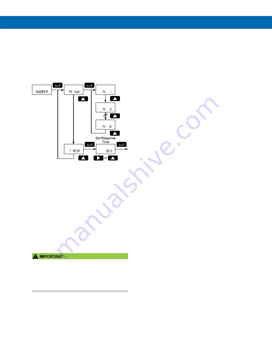
Snooper Mode PV Configuration
(
PV NUM
)
The
PV Number
menu is used to enable and disable
each Modbus PV 1 to 16. This menu is identical in
Master mode. Refer to
Snooper Mode Response Time
(
T RESP
)
If the Modbus data registers for the enabled Modbus
PVs are not updated within a certain period of time,
the scanner can presume that there is an error with
the data. After this time has passed, and updated
data has not been detected on the Modbus network,
the scanner will display this PV as NONE (
NONE
).
At the
Response Time
menu, enter the time limit the
scanner will display the Modbus PV register last data
monitored before it assumes an error.


