background image


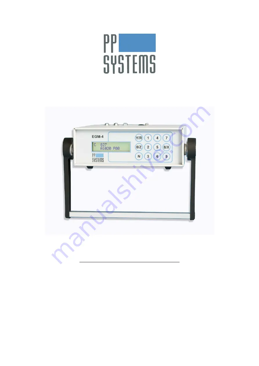
EGM-4 Environmental Gas 

Monitor For CO

2


Operator’s Manual 

Version 

4.19


For Firmware (EPROM) Version 1.46 and Greater 

© 2012 PP Systems.  All Rights Reserved 


14 February 2013 


PP Systems 

110 Haverhill Road, Suite 301 

Amesbury, MA 01913 U.S.A. 

Tel:  +1 978.834.0505  

Fax:  +1 978.834.0545 


Email: 

[email protected] 


Web Site: 

http://www.ppsystems.com 

Summary of Contents for EGM-4

Page 1: ...4 19 For Firmware EPROM Version 1 46 and Greater 2012 PP Systems All Rights Reserved 14 February 2013 PP Systems 110 Haverhill Road Suite 301 Amesbury MA 01913 U S A Tel 1 978 834 0505 Fax 1 978 834...

Page 2: ...This page left intentionally blank for printing purposes...

Page 3: ...ery 14 CHARGING THE INTERNAL 12V NiMH BATTERY 15 Charge Cycle and LED Indications for 12V NiMH Battery Charger 15 Charge Socket 15 Power Supply Charger 15 Power Switch 16 Operation 17 Main Menu 19 1RE...

Page 4: ...Serial Outputs 41 5CLR 41 6CLK 42 Diagnostics and Initialisation 43 Diagnostics 43 Initialisation 43 Maintenance 44 Soda Lime Absorber Column 44 Soda Lime 44 MATERIAL SAFETY DATA FOR SODA LIME 45 Ser...

Page 5: ...n 3CAL on page 35 of this manual All calibration related questions may be directed directly to PP Systems at Telephone 1 978 834 0505 Fax 1 978 834 0545 Email support ppsystems com User Registration I...

Page 6: ...ent is properly installed operated and maintained in accordance with written instructions i e Operator s Manual The warranty excludes all defects in equipment caused by incorrect installation operatio...

Page 7: ...to CO2 If this is placed in line in the analysis pipe at the sampling point the water vapor concentration of the analysis air will be brought close to ambient Part No 10049 1 Water Vapor Equilibrator...

Page 8: ...c Air Filter Filtered sample line hydrophobic Calibration Default value preset in factory Built in Initialization Automatic calibration via keypad if required CO2 Control High and low set points Alarm...

Page 9: ...icrons A source emitting strongly at this wavelength is a light bulb If this is positioned at one end of a tube and at the other end is placed a sensor that is sensitive to photons at 4 26 microns we...

Page 10: ...ator s Manual Version 4 19 10 Getting Familiar With The EGM 4 Front Panel Figure 1 EGM 4 Display Front Panel LCD Display 2 x 16 Character Custom tactile keypad Sensor I O Connectors RS232 Connector Ga...

Page 11: ...Getting Familiar With The EGM 4 EGM 4 Operator s Manual Version 4 19 11 Top of EGM 4 Back Panel of EGM 4 fitted with 12V Lead Acid Battery Back panel of EGM 4 fitted with 12V NiMH Battery...

Page 12: ...s determined by keypad selection 1 STP 1 Soil Temperature Probe 100 K 2 Not Applicable Used to be used with older sensors 56 K 3 TRP 1 TRP 2 Temperature PAR Probe 36 K 4 PAR 1 PAR Sensor 27 K 5 Not Ap...

Page 13: ...other connections are required to get a 4 20 mA output from the EGM 4 Applying voltage to the Iout pins higher than 12 V will damage the internal circuitry RS232 Port The EGM 4 has one 9 pin RS232 co...

Page 14: ...ys There are ten keys that are labelled 0 9 Also there are a few keys that have additional functions The Y R Yes Record key is used to accept settings and to record measurements In addition the Y R ke...

Page 15: ...ons for 12V NiMH Battery Charger LED Mode Orange Battery not connected Orange Battery initialization analysis Red Fast charge Green with intermittent orange flash Top off charge Green Trickle charge A...

Page 16: ...PP SYSTEMS FOR THE EGM 4 WILL INVALIDATE THE WARRANTY Please note EGM 4 s can also be powered by an internal rechargeable 12V NiMH battery for extended operation in the field For more information on t...

Page 17: ...eaches 50 C A final Zero check is then performed before proceeding to the Main Menu Also during warm up several system checks are performed The Checksum message is set to a factory default value of 12...

Page 18: ...cified by the end user 5V 2000 Range of the voltage signal corresponding to the CO2 concentration POROMETER Refers to the PMR 5 R150 Number of records stored in memory After all system checks have bee...

Page 19: ...ted See Stand Alone CO2 Analyzer Probe Type 0 on page 20 0 Environmental Monitor With one of our Environmental Sensors such as RH temperature PAR O2 etc See Environmental Monitor Probe Types 1 6 and 1...

Page 20: ...ensor is present A Absolute pressure in sample cell mb P Refers to probe type See 1REC on page 19 To return to the Main Menu while in Measurement Mode simply press the N key Note If the instrument was...

Page 21: ...2 Where REC Record Number PLOT Plot Number 19 12 Date 19 th day of December 13 05 Time 1 05 PM Press Key 8 to display the following Display 3 Where A Signal mV from sensor connected to Pin 1 on the 15...

Page 22: ...the EGM 4 press key 8 X to see the humidity displayed in mb Note If the instrument was just powered up the display will show WARM UP DELAY TEMPERATURE XX until the instrument achieves its warm up temp...

Page 23: ...ecord Number up to 9999 PLOT Plot Number up to 99 03 04 Date 3 rd day of April 12 40 Time 12 40 PM Note If the plot number needs to be changed press key N when Display 2 above is shown and enter the p...

Page 24: ...used in fitting the soil respiration rate curve or the final results If you want to save the full set of data press key 1 Note data is collected every 4 8 seconds If 1 is selected ALL the internal mem...

Page 25: ...air temperature C 4SRDIV 2 Only available from firmware version 1 51 and above Prior to V 1 51 a divisor of 100 was used to convert the four digit SR number in soil respiration units in g m 2 hr limit...

Page 26: ...is present mb T22 Soil Temperature if optional STP 1 probe is present C A02 11 CO2 exchange Assimilation rate g CO2 m 2 Hour The maximum rate that can be recorded is 99 99 g CO2 m 2 Hour Q0000 PAR mol...

Page 27: ...1 Soil Respiration Chamber or CPY 4 technical documentation Oxygen Probe Type 9 Immediately after pressing key 1 the instrument will automatically perform a zero check Once completed and assuming no...

Page 28: ...isplay 2 Where REC Record Number up to 9999 PLOT Plot Number up to 99 03 04 Date 3 rd day of April 12 40 Time 12 40 PM Note If the plot number needs to be changed press key N when Display 2 above is s...

Page 29: ...esponse Time minutes Chamber Volume 2 2litres Flow Rate litres minute So at a Flow Rate of 1litre minute System Response Time 2 2 minutes Assuming the system is perfectly mixed then there is an expone...

Page 30: ...tand alone gas analyzer part of an environmental monitoring system when used with any of our available sensors i e TRP 2 SRC 1 Soil Respiration Chamber CPY 4 Canopy Assimilation Chamber etc or as a st...

Page 31: ...fter 2 minutes then again after 4 more minutes then after 8 minutes and finally after 16 minutes up to a maximum interval set by the ZEROTIME ZEROTIME by default at start up is 20 minutes but it can b...

Page 32: ...ning on for a ZERO On completion of the Analyzer ZERO the pump will again switch off By default the EGM 4 is set to dynamic sampling with the pump on at all times The general procedure for static meas...

Page 33: ...rding press key 2 and enter a value not to exceed 720 minutes Note leading zeros are required for values less than 100 i e 005 for 5 minutes The EGM 4 is set to MANUAL recording by default 6ALM There...

Page 34: ...As long as the high alarm is set to the maximum CO2 ppm range of the instrument the alarm is inactive If set to a lower value when the CO2 concentration exceeds the high setting the alarm will activat...

Page 35: ...been scrubbed through soda lime 2 Span Gas a user defined CO2 concentration normally a cylinder of certified CO2 composition It is therefore vital that both of these references are accurate For great...

Page 36: ...i e not changing by more than 1 ppm after 30 seconds press the 0 key Control is passed to the VOUT Set Menu to provide the opportunity to change the scale factor if desired If no change is desired pre...

Page 37: ...f you are only interested in viewing the CO2 concentration for each record 1 Press key 4 4DMP 2 Press key 1 Screen Display 3 Press the 8 key to display the CO2 concentration for the last stored record...

Page 38: ...re supplied by PP Systems please refer to the on line help menus built into the software Record Structure A single record consists of 61 characters no spaces The last character is a carriage return Re...

Page 39: ...000 RH 0000 Air Temp 000 0 4 PAR 1 PAR Sensor PAR 0000 5 PAR 1 LUX 6 Solarimeter 7 Steady State Porometer PMR 4 PMR 5 PAR 0000 RH In 000 0 Temp 000 0 RH Out 000 0 Flow 000 0 GS 0000 8 SRC 1 Soil Respi...

Page 40: ...ource detector failure Refer to Air Sampling Pump on page 51 Fit properly into manifold Change soda lime Contact PP Systems see PP Systems Contact Information on page 7 Contact PP Systems see PP Syste...

Page 41: ...the same as the count on the EGM display During Warm up SP W TT CR Where TT is the cell temperature During ZERO SP Z NN CR Where NN is the same as the EGM display count During Diagnostics a data strin...

Page 42: ...e EGM 4 real time clock press the 6 key The following message should be displayed The date is displayed as day month year and the time is displayed on a 24 hour format The display above shows December...

Page 43: ...column The Z value should always be greater than the CR value 0 Z Press key 0 to perform an Auto Zero Press Key N to return to the Main Menu Initialisation This feature is available in the event of a...

Page 44: ...replaced as found Over time the grey foam filter may require replacement If so contact PP Systems PP Systems Contact Information on page 7 It is sensible to examine the absorber column each time the...

Page 45: ...e away from direct heat sun Protective Measures Avoid inhaling dust Wash hands after handling Industrial Hygiene Keep containers closed Keep contents dry MEASURES IN CASE OF ACCIDENTS AND FIRES Spilla...

Page 46: ...to determine if a fuse is good or bad Usually a bad fuse will be burned out and visually obvious The true test is to use an ohm meter Place one lead from the ohm meter on one end of the fuse and the...

Page 47: ...N13 Source by pulling up on it 3 Remove the 4 small screws that secure the infrared source to the end of the sample cell and remove it 4 Fit the new infrared source to the end of the sample cell align...

Page 48: ...ent to perform a single point calibration with a reference gas if possible See 3CAL on page 35 EPROM The firmware and factory measured calibration factors for the EGM 4 are stored on a memory chip com...

Page 49: ...hat the 1A fuse is ok This fuse protects the charging circuit and if blown the internal battery will not take a charge Please Note The internal 12V battery should always be fully charged before long t...

Page 50: ...internal 12V NiMH battery will slowly discharge over time regardless of the state of charge Therefore you must ensure that you charge the instrument fully prior to next use 12V NiMH Battery Specificat...

Page 51: ...itting of the pump The pump itself is secured in position by the gas tubing connections Finally remove the tubing from the inlet and outlet ports on the pump and lift out Fit the new pump making sure...

Page 52: ...s dry outside of the EGM 4 overnight If the pumps are reconnected prematurely the absorber chemical soda lime will be exhausted quicker than usual In Line Filter Assembly Hydrophobic The In Line Filte...

Page 53: ...O Ring for Absorber Column Plug 20041 3 Absorber Column for EGM 4 STD076 Sealed Miniature Rotary Pump ASF 30032 1 Solenoid Valve SBA 4 EGM 4 WMA 4 PC073 1 EGM SBA WMA Infra Red Source Low Range Instr...

Page 54: ...User Notes EGM 4 Operator s Manual Version 4 19 54 User Notes...

Reviews: