background image

13

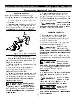
Light Bulb Replacement

To prevent             

damage to light, 

do not operate light for longer than 15 

minutes.

1.

Remove the two screws that hold the lens

against the winch cover.

2.

Remove gasket and inspect for tears or

dam-age, replace if necessary.

3.

Rotate the expired light bulb a 1/4 turn or

90 degrees inside the clips and pull out.

4.

Replace with new light bulb and reinstall

gas-ket, lens and hardware. The light bulb


is

a 212-2 automotive bulb.

Operating Instructions and Replacement Parts List

Deckmate 25 Freefall Pontoon Windlass

Maintenance

Periodic maintenance to the Free Fall 

Pontoon Windlass will help to extend the 

service life of the equipment and the 

following steps can be taken to do this.

Always disconnect power to the windlass 

at  the  battery  before


preforming  any 

maintenance on the unit.

1.

Lubricate the gear train with a lithium

grease at the beginning of each boating

season.

2.

Lubricate the shaft on the davit roller with

a small amount of lithium grease at the

beginning of each boating season.

3.

Inspect the anchor line at the beginning of

each boating season.


Replace the 3/16”

diameter, 3 strand nylon rope if it is frayed,

cut or kinked. When replacing the rope refer

to the following 

instructions

.

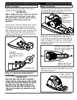
Anchor Line Replacement


Make sure that the windlass is in the free fall 

mode of operation


Next, disconnect the 

power to the windlass at the battery.


Locate 

the portion of the rope that inserts through the 

hole of the rope spool.


Push on this end so 

that the knotted portion of rope on the 

opposite side of the flange is pushed out of 

the counter bore and is exposed.


Take a thin 

screwdriver or flexible piece of wire and pull 

the knotted rope end out from between the 

frame and rope spool flange.


Untie the knot 

or cut the rope just below the knot and pull 

the rope out of the spool.

Take the new rope and hold onto the non 

looped end and throw the rope out into the 

water.


Follow the illustration in Figure 22 to 

install the rope onto the spool.  

Note: The illustrations in Figure # depict the 

rope spool unattached to the wind-lass for 

clarity purposes.  The rope spool can be left 

assembled to the windlass when replacing 

the rope.  

Reconnect the power to the windlass at the 

battery

Finally, wind the rope onto the rope 

spool while being careful to maintain even 

wraps of rope as it winds.

PULL THE 

END OF ROPE 

THROUGH AND 

TIE END IN 

KNOT

ROPE WINDS ONTO 

THE SPOOL OVER THE 

TOP 

PULL KNOT 

FIRMLY INTO 

PLACE IN 

THE COUN-

TER BORED 

RECESS OF THE 

FLANGE

INSERT END 

OF ROPE INTO 

HOLE IN ROPE 

SPOOL

OUT TO ANCHOR

ROPE 

SPOOL

ROPE 

Figure 22

Summary of Contents for Deckmate 25 Free Fall Pontoon Windlass

Page 1: ...on of the time that it takes a traditional power down windlass The built in light assists retrieving anchors and launching or retrieving the boat at night Unpacking When unpacking inspect carefully fo...

Page 2: ...s disconnect the wiring harness from the battery before attempting to install relocate or service the winch or switch Cruising and boat trailering hazards 1 When the boat is cruising or being trailere...

Page 3: ...bow roller comes unassembled in the packaging with the windlass Locate the parts shown below before start ing the assembly 3 Operating Instructions and Replacement Parts List Deckmate 25 Free Fall Pon...

Page 4: ...ST070932AV WASHER P10951 BOW ROLLER HOUSING P55704 HEX NUT ST070932AV WASHER FIGURE 2 ASSEMBLING ROLLER INTO HOUSING FIGURE 3 COMPLETELY ASSEMBED BOW ROLLER Insert P55712 Bow Roller Spacer into P55710...

Page 5: ...Replacement Parts List Deckmate 25 Free Fall Pontoon Windlass STEP 1 Continued FIGURE 4 Bow roller assembly assembled to bow of boat Cut away view IMPORTANT BEFORE DRILLING HOLES TO MOUNT WINCH MECHAN...

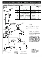
Page 6: ...cation of the switch 1 Locating the switch on the helm will allow the boat to be steered toward the anchor point when the winch is being used 2 Locating the switch on the helm will require extra wirin...

Page 7: ...n in Figure 12 Figure 12 Switch Plate Assembly Rocker Switch Switch Plate Rear view of switch Make sure angled terminals are located as shown Top of Switch Plate 4 Locate push button switch for light...

Page 8: ...wire P55801 2 B 10 ring terminal for 8 gage wire ST072730AV 2 C 5 16 ring terminal for 8 gage wire ST072732AV 6 D Red switch wire assembly P44071 2 E Black switch wire assembly P44072 2 F 5 16 ring te...

Page 9: ...rubber boot that ts over switch and assemble as shown in Figure 17 Switch Boot Push Button Switch Figure 17 Light Switch Assembly Insert push button switch through hole in switch plate and secure with...

Page 10: ...55801 2 B 10 ring terminal for 8 gage wire ST072730AV 2 C 5 16 ring terminal for 8 gage wire ST072732AV 6 D Red switch wire assembly P44071 2 E Black switch wire assembly P44072 2 F 5 16 ring terminal...

Page 11: ...unting the switch to the winch cover locate the four screws that are needed to secure the switch plate in Figure 17 and assemble them as shown in Figure 20 Secure switch plate using screws in kit Figu...

Page 12: ...spot has been located and the depth of the water is estimated the anchor can be dropped 2 Turn the the boat into the wind and put the mo tor in neutral 3 Once the boat has stopped all forward progres...

Page 13: ...g the rope refer to the following instructions Anchor Line Replacement Make sure that the windlass is in the free fall mode of operation Next disconnect the power to the windlass at the battery Locate...

Page 14: ...Promptly notify the Seller or the Company of any claim hereunder 3 At the Option of the Company return the Product to the Company for inspection Authorization must be given prior to any Product retur...

Page 15: ...tn Customer Service 2268 Fairview Blvd Fairview TN 37062 Operating Instructions and Replacement Parts List Deckmate 25 Freefall Pontoon Windlass 1 2 3 4 5 5 6 7 8 9 10 11 ITEM PART DESCRIPTION QTY 1 P...

Page 16: ...5 16 18 1 24 P10273 WASHER 1 4 ID 1 3 2 22 25 24 11 12 4 6 10 7 29 20 23 14 1 26 13 27 31 19 28 33 32 18 34 8 9 15 5 17 16 21 30 35 36 37 38 39 40 ITEM PART DESCRIPTION QTY 25 P79520 HHCS 1 4 20 X 50...

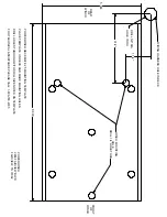
Page 17: ...E THRU 31 2 DRILL 5 8 DIA 1 1 4 9 000 5 000 FRONT OF WINCH WINCH MOUNTING HOLE DRILL 1 4 HOLE THRU POWERWINCH DECKMATE 25 MOUNTING TEMPLATE PLACE TEMPLATE ON DECK AND MARK MOUNTING HOLES DRILL HOLES T...

Reviews: