Operating Instructions and Replacement Parts List
De
c
kmate 25 Free Fall Pontoon Windlass
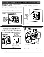
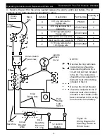
3. Refer to Figure 18 for the wiring needed between the winch, switch and battery.
The kit
contains all the parts needed to complete the wiring.
Winch
Motor
Green
Wire
Black
Wire
F
F
D
D
C
C
B
B
A
A
Light In
Winch
Cover
Push
Button
Light
Switch
12 Volt DC
Battery
+
-
Circuit
Breaker
(25A)
8 GA
Black Wire
8 GA
Red Wire
8 GA
Red Wire
Minimum
12” Long
Symbol
Description
Part Number Quantity in
Kit
A
3/8” ring terminal for
8 gage wire
P55801
2
B
#10 ring terminal for 8
gage wire
ST072730AV
2
C
5/16” ring terminal for
8 gage wire
ST072732AV
6
D
Red switch wire assembly
P44071
2
E
Black switch wire assembly
P44072
2
F
5/16” ring terminal for
10-12 gage wire
ST072726AV
6
Winch Switch
(rear view)
NOTES:
Denotes the ring terminals
inside the box should be
connected together with a
1/4-20 bolt and nut
included
in the kit. The connection
should then be sealed with 1”
diameter heat shrink tubing
included in the kit.
Denotes the circuit breaker
should be sealed with the 2”
diameter heat shrink tubing
included in the kit after it has
been connected to the wiring
from the winch and battery
Figure 18
Wiring Diagram for
Mounting Switch on
Winch Cover
10
E
E


