WEBS-5481
Fan-less Embedded System
User's Manual
Version 1.0
Copyright © Portwell, Inc., 2015. All rights reserved.
All other brand names are registered trademarks of their respective owners.
Page 1: ...WEBS 5481 Fan less Embedded System User s Manual Version 1 0 Copyright Portwell Inc 2015 All rights reserved All other brand names are registered trademarks of their respective owners ...
Page 2: ...ules 2 2 2 4 I O Interfaces 2 4 2 4 1 Front View 2 4 2 4 2 Rear View 2 5 2 5 Getting Started 2 7 Chapter 3 BIOS Setup Information 3 1 3 1 Entering Setup Launch System Setup 3 1 3 2 Main 3 2 3 3 System Setup Utility 3 3 3 4 Configuration 3 3 3 5 Boot 3 22 3 6 Security 3 24 3 7 Exit 3 25 Chapter 4 Important Instructions 4 1 4 1 Note on the Warranty 4 1 4 2 Exclusion of Accident Liability Obligation ...
Page 3: ...of all the interfaces and describe a proper installation guide so that you can easily configure your system Chapter 3 BIOS Setup Information Specify the meaning of each setup parameters how to get advanced BIOS performance and update new BIOS In addition POST checkpoint list will give users some guidelines of trouble shooting Chapter 4 Important Instructions Indicate some instructions which must b...
Page 4: ...sistance attributes the fan less and rugged WEBS 5481 excels in harsh environments WEBS 5481 also offers clear and concise video and graphics capabilities because it takes full advantage of the 4th generation Intel Core processor with integrated HD4400 graphics engine which outperforms its predecessor by over 20 In addition to the built in triple display interfaces two additional display devices a...
Page 5: ...or and keep all packing materials for future replacement and maintenance 1 3 Product Specification System M B PEB 5731 System Chipset Intel Haswell ULT SoC CPU Intel Core i7 4650U 1 7GHz 4M L2 Cache up to 3 3GHz 15W TDP 2C 4T Intel Core i5 4300U 1 9GHz 3M L2 Cache up to 2 9GHz 15W TDP 2C 4T Intel Core i3 4010U 1 7GHz 3M L2 Cache 15W TDP 2C 4T Intel Celeron 2980U 1 6GHz 2M L2 Cache 15W TDP 2C 2T BI...
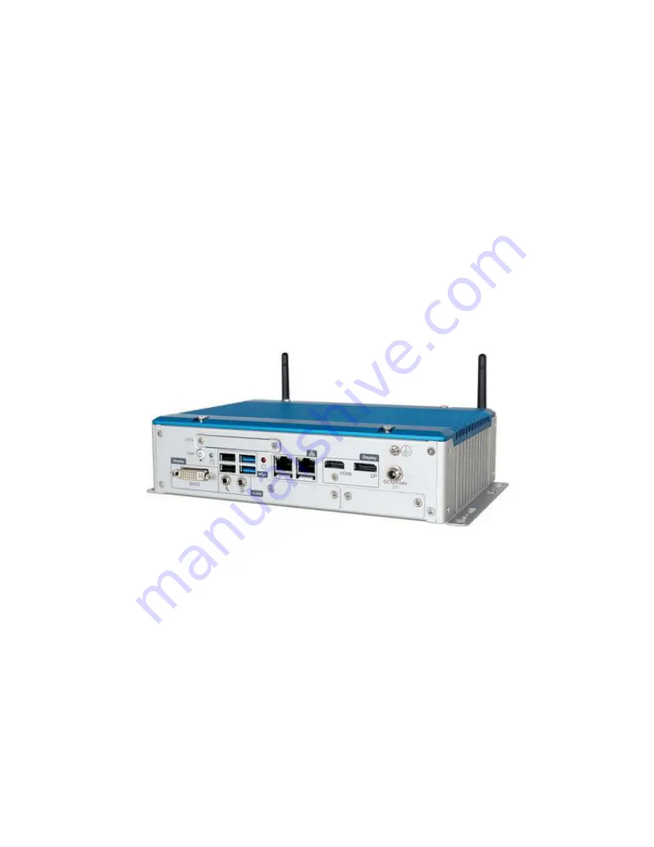
Page 6: ...ule Power Supply Unit Power Supply DC 12 24V Environment Operating Temperature 20 to 55 Storage Temperature 40 to 80 Relative Humidity 95 40 non condensing Operating Vibration 5Grms 5 500Hz IEC 60068 2 64 Operating Shock 50G 11 msec IEC 60068 2 27 Mechanical Dimension WxDxH 253 x 160 x 60 mm 9 2 x 6 2 x 4 Weight 2 kg Mounting Wall Mount 1 4 Mechanical Dimension Front view of the WEBS 5481 system R...
Page 7: ...System Overview WEBS 5481 User s Manual 1 4 Top view of the WEBS 5481 system Side view of the WEBS 5481 system ...
Page 8: ...tem For more detailed PIN assignment and jumper setting please refer to user s manual of PEB 5731 W 2 1 HDD Installation HDD cover locates at the back of the system Step 1 Turn the system upside down Step 2 Unscrew the HDD cover Step 3 Take out the HDD cover Step 4 Install the HDD onto cover Step 5 Plug the SATA and power cable to connect the M B and HDD Note Glue it if needed Step 6 Screw the HDD...
Page 9: ...he CFEX cover Step 2 Take the CFEX card Step 3 Insert the CFEX card into the slot Step 4 Finish installation 2 3 Replacement of Additional Graphic Modules In addition to the built in triple display interfaces two additional display devices are made available by Portwell s graphics modules thus the WEBS 5481 system can support up to five display outputs by extended mode in the OS Note Modules must ...
Page 10: ...tray of graphic module Step 5 Connect the cable to graphic module with which you want to replace and lock it Step 6 Install the tray of graphic module back onto the system Step 7 Screw the tray of graphic module properly Step 8 Finish installation Note Drivers should be installed properly to run the feature ...
Page 11: ...le GPIO GPIO PIN Definition PIN No Signal Description PIN No Signal Description 1 EC_GPI0 2 GPO0 Voltage from JP6 3 EC_GPI1 4 GPO1 Voltage from JP6 5 EC_GPI2 6 GPO2 Voltage from JP6 7 EC_GPI3 8 GPO3 Voltage from JP6 9 GND 10 VCC5 11 N A 12 N A 13 N A 14 N A 15 N A X X GPIO Output Voltage JP6 Function 1 2 Short 5V 2 3 Short 3 3V Default ...
Page 12: ...te RS 232 422 485 configuration is determined by BIOS setting Check BIOS setting for details PIN No Signal Description 1 DCD DT 2 RXD DT 3 TXD 422R 4 DTR 422R 5 GND 6 DSR 7 RTS 8 CTS 9 RI 2 4 2 Rear View DC in Wide range DC source support 12 24V Using the provided DC source to connect to the system Power Button Press the power button to turn ON OFF the system ...
Page 13: ... by Portwell and adapting legacy CF type one with advanced pin definitions This helps overcome reliability issues with standard commercial memory CFEX also supports SATA 3 0 SPI and other extensions and achieves a read speed of 100 to 120Mbyte s and write speed of 45 to 75Mbyte s Compared with other CF devices it falls in the same low cost bracket as CF and CF SATA and is less expensive than CFAST...
Page 14: ...nual 2 7 2 5 Getting Started It is easy to get the system started Step 1 Make sure the power supply 12 24V is connected properly Step 2 Press the power button to turn on the system Note Power LED shines BLUE when system is ON ORANGE when OFF ...
Page 15: ...figuration information stored in the CMOS memory If any error is detected or the CMOS parameters need to be initially defined the diagnostic program will prompt the user to enter the SETUP program Some errors are significant enough to abort the start up 3 1 Entering Setup Launch System Setup Power on the computer and the system will start POST Power On Self Test process When the message below appe...
Page 16: ...mory specifications of your system Build Time The BIOS Release Date Processor Brand Name Processor Speed This value will change depend of different CPUs And please make sure the Processor that you ll install will be compatible with PEB 5731 User s Manual System Date The date format is Day Month Date Year Use or to configure system Date System Time The time format is Hour Minute Second Use or to co...
Page 17: ...related BIOS settings Table 1 System Setup Utility menus Menu Usage Main Display a summary of the system and configure the system date and time Configuration Configure the system interfaces system management power management thermal management and other system characteristics Boot Configure boot device priority settings Security Configure user authentication requirements Save Exit Save changes and...
Page 18: ...her OS Active Processor Cores All Default 1 Select the number of physical cores to enable in each processor package Intel Virtualization Technology Disabled Enabled Default When enabled a VMM can utilize the additional hardware capabilities provided by Vanderpool Technology EIST Disabled Enabled Default Enabled Disabled Intel SpeedStep Turbo Mode Disabled Enabled Default Turbo Mode CPU C states Di...
Page 19: ... not necessary to make any change just take the default value BIOS Item Usage Item Specific Help High Precision Timer Disabled Enabled Default Azalia Disabled Enabled Default VT d Disabled Default Enabled Enabled Disabled VT d function on MCH Port 80h Redirection LPC Bus PCIE Bus ...
Page 20: ... WEBS 5481 User s Manual 3 6 AMT Configuration BIOS Item Usage Item Specific Help Intel AMT Disabled Enabled Default Disables Enabled iAMT function Un Configure ME Disabled Default Enabled Disable ME Disabled Default Enabled ...
Page 21: ...BIOS Setup Information WEBS 5481 User s Manual 3 7 Memory Configuration ...
Page 22: ...cific Help Launch PXE OpROM Policy Disabled Default Enabled Intel LAN I218 Controller Disabled Enabled Default Enable Disable Intel LAN I218 Wake on LAN Disabled Default Enabled Intel LAN I210 Controller Disabled Enabled Default Enable Disable Intel LAN I210 Wake on LAN Disabled Default Enabled ...
Page 23: ...be Primary Display or select Secondary Display for switchable Graphics Internal Graphics Auto Disabled Enabled Default Keep IGD Enabled based on the setup options Aperture Size 128MB 256MB Default 512MB Select the Aperture Size DVMT Pre Allocated 32M 64M 96M 128M 160M 192M 224M 256M Default 288M Select DVMT 5 0 Pre Allocated Fixed Graphics Memory size used by the internal Graphics Device ...
Page 24: ...otal Gfx Mem 128MB 256MB Default MAX Select DVMT5 0 Total Graphics Memory size used by the Internal Graphics Device Primary IGFX Boot Display VBIOS Default HDMI DVI Default DP Secondary IGFX Boot Display VBIOS Default HDMI Default DVI DP DVI Display Type 1024x768 Default 1280x1024 1360x768 1920x1200 ...
Page 25: ... Item Usage Item Specific Help PCI Latency Timer 32 PCI Bus Clocks 64 PCI Bus Clocks 96 PCI Bus Clocks 128 PCI Bus Clocks 160 PCI Bus Clocks 192 PCI Bus Clocks 224 PCI Bus Clocks 248 PCI Bus Clocks Maximum Payload Auto 128 Bytes 256 Bytes 512 Bytes 1024 Bytes 2048 Bytes 4096 Bytes Maximum Read Request Auto 128 Bytes 256 Bytes 512 Bytes 1024 Bytes ...
Page 26: ...BIOS Setup Information WEBS 5481 User s Manual 3 12 2048 Bytes 4096 Bytes PCH PCI Express Configuration It is not necessary to make any change just take the default value ...
Page 27: ...ary to make any change just take the default value BIOS Item Usage Item Specific Help PCI Express Root Port 1 2 4 6 Disabled Enabled Default Control PCI Express root port ASPM Disabled Default L0S L1 L0S L1 Auto Control PCIe Active State Power Management setting PCIe Speed Auto Default Gen1 Gen2 Select PCIe Speed to Gen1 or Gen2 ...
Page 28: ...ed Default Disabled Determines how SATA controller s operate SATA Mode Selection Disabled IDE AHCI Default RAID Determines how SATA controller s operate SATA Controller Speed Default Gen1 Gen2 Gen3 Default Port 0 3 Disabled Enabled Default Hot Plug Disabled Default Enabled External SATA Disabled Default Enabled SATA Device Type Hard Disk Drive Solid State Drive Default ...
Page 29: ...USB controller and other advanced setting BIOS Item Usage Item Specific Help Legacy USB support Enabled Default Disabled Enables Legacy USB support AUTO option disables legacy support if no USB devices are connected DISABLE option will keep USB devices available only for EFI applications XHCI Mode Smart Auto Default Auto Enabled Disabled Manual XHCI Hand off Enabled Default Disabled ...
Page 30: ...CI Hand off Enabled Disabled Default USB Mass Storage Driver Support Enabled Default Disabled PCH USB Configuration USB Ports per Port 0 7 Disable Disabled Default Enabled Control each of the USB ports disabling PCH USB Configuration USB Ports per Port 0 7 ...
Page 31: ...nate Funtion ACPI Sleep State S3 Only Suspend to RAM Select the highest ACPI sleep state when the SUSPEND button is pressed Power loss function Always Off Default Always On Last State Select AC Power state when power is re applied after a power failure Wake system with Fixed Time Disabled Default Enabled Enable or disable System wake on alarm event When enabled System will wake on the hr min sec s...
Page 32: ...tion WEBS 5481 User s Manual 3 18 TPM Configuration BIOS Item Usage Item Specific Help Security Device Support Disabled Default Enabled Enabled Disabled TPM Function Super IO Configuration Enable Disable Watch Dog Timer ...
Page 33: ...t 0 6 Configuration BIOS Item Usage Item Specific Help WDT Controller Disable Default Enabled Timer Unit Second Default Minute Timer value 20 Default Serial Port 1 6 Disable Enable Default Setting Serial Port 1 6 RS 232 422 485 Control Option RS 232 RS 422 RS 485 ...
Page 34: ...rdware Monitor Provide on board sensor reading information BIOS Item Usage Item Specific Help CPU Smart Fan Control Disable Default Enable Smart Fan Start Temperature 50 Default Disable Enable Smart Fan function Smart Fan Full Speed Temperature 50 Default ...
Page 35: ...ial Port Console Configuration Configure console redirection on serial port BIOS Item Usage Item Specific Help Serial Port 1 Console Redirection Disabled Default Enabled Control Console Redirection enable disable Console Redirection Disabled Default Enabled ...
Page 36: ...IOS service ALWAYS do not allow disabling GA20 this option is useful when any RT code is executed above 1MB Choices Upon Request Always Option ROM Messages Set Display mode for Option ROM This item is used to determine the display mode when an optional ROM is initialized during POST When set to Force BIOS the display mode used by AMI BIOS is used Select Keep Current if you want to use the display ...
Page 37: ...ble When Disabled the ROM BIOS of these host adaptors will not be able to capture Interrupt 19 Therefore you will not be able to boot operating systems from any bootable disks attached to these host adaptors Nor will you be able to gain access to their ROM setup utilities Choices Disabled Enabled Launch Storage OpROM Choices Disabled Enabled Full Screen Logo Choices Disabled Enabled Post Report Ch...
Page 38: ...BIOS Setup Information WEBS 5481 User s Manual 3 24 3 6 Security Set or clear the Supervisor account s password Administrator Password Set Setup Administrator Password User Password Set User password ...
Page 39: ... of all menu then exit setup configure driver Finally resets the system automatically Save Changes and Exit Exit system setup after saving the changes Discard Changes and Reset Reset the system without saving the changes Restore Defaults Restore Load Default Values for all the setup options ...
Page 40: ...aused by failure to abide by the hints in this manual and on the unit especially the safety instructions Portwell Inc shall not be required to respect the warranty even during the warranty period and shall be free from the statutory accident liability obligation 4 4 Declaration of Conformity EMC CE FCC Class A This equipment complies with Part 15 of the FCC Rules Operation is subject to the follow...