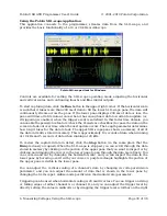
side of the lower pane to the desired position. When triggering is enabled, the data in the
lower pane will update whenever a trigger event occurs. Triggering can help you to better
identify and analyze periodic signals (such as motor noise, PWMs, etc.) while the SLO-scope
is running.
To change the color used to draw a channel’s data, double click on the colored square in
either the Channel A or Channel B box.
To change the vertical position of the 0V level of a channel, click and drag that channel’s
corresponding 0V-indicator triangle on the left side of the lower pane.
While the SLO-scope is running, lines
A
and
B
do not function as serial handshaking lines as
discussed in
. Rather, the SLO-scope can control the I/O states of
A
and
B
. The
SLO-scope application lets you configure these pins as inputs (their default settings when
you first enable the SLO-scope) or as digital outputs driven high or low.
Pololu USB AVR Programmer User's Guide
© 2001–2010 Pololu Corporation
6. Measuring Voltages Using the SLO-scope
Page 31 of 36


