POLITEC s.r.l. | Manual PARVIS HYBRID SMA – Ver. 1.2
4
2.
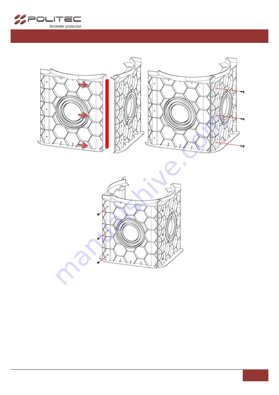
ASSEMBLING THE CABLEPIT
1.
Insert the highlighted edge into other section and fix with screws
Insert the third section in the same way and fix with screws.
Page 1: ...Technical manual...
Page 2: ...CS Pag 23 Installation recommendation Verify that the beam tower is fully watertight once the cover and end caps have been correctly filled at the end of the installation Use the cable glands supplied...
Page 3: ...14 13 12 1 MAIN COMPONENTS N Description 1 Aluminium pole 2 Pipe IR 3 Plug 4 Lamp adapter 5 Base 6 Cablepit 7 Motherboard TX 8 Group optic TX RX 9 Motherboard RX 10 Cover for the base 11 Battery rech...
Page 4: ...ITEC s r l Manual PARVIS HYBRID SMA Ver 1 2 4 2 ASSEMBLING THE CABLEPIT 1 Insert the highlighted edge into other section and fix with screws 2 Insert the third section in the same way and fix with scr...
Page 5: ...POLITEC s r l Manual PARVIS HYBRID SMA Ver 1 2 5 3 Enlarge the two opposite walls of cable pit to allow the positioning of last section 4 Insert and well fix the missing screws...
Page 6: ...the following way cement all around the cable pit keeping the top edge of it at same level of ground For PARVIS columns is also possible to keep the top edge ten centimeters below the level of the gro...
Page 7: ...be perpendicular to the ground If the base is not in perfectly at ground level is possible to adjust it through the insert regulation of cable pit On the side that must be corrected loosen the insert...
Page 8: ...ll the cables to and from the PARVIS tower passes through the supplied cable glands inserted into the base cap Use the central cable gland for lightning cable Base cover with the cable glands and O ri...
Page 9: ...MPLES Per un installazione a controllo di perimetro posizionare le barriere come indicato Note if you use the optical sync do not place multiple transmitters on the same line in the same direction 4 B...
Page 10: ...POLITEC s r l Manual PARVIS HYBRID SMA Ver 1 2 10 5 WIRING 220 Vac 12 Vdc THERMOSTAT BOARD POWER SUPPLY BOARD 3 6V MOTHERBOARD TX or RX...
Page 11: ...TEC s r l Manual PARVIS HYBRID SMA Ver 1 2 11 6 CONFIGURATION OF THE OPTICALS OPTICAL TX NB The address settings as per default 1 2 3 4 5 6 1 2 3 4 5 6 TX1 TX2 TX3 TX4 TX5 TX6 TEST LED TAMPER TEST BUT...
Page 12: ...POLITEC s r l Manual PARVIS HYBRID SMA Ver 1 2 12 OPTICAL RX 1 2 3 4 5 6 1 2 3 4 5 6 RX1 RX2 RX3 RX4 RX5 RX6 NB The address settings as per default TAMPER LOW SIGNAL LED TEST LED TEST BUTTON...
Page 13: ...POLITEC s r l Manual PARVIS HYBRID SMA Ver 1 2 13 7 SANDOR WS SMA TX MOTHER BOARD N B When the motherboard is supplied the LED ON will flash LED ON TAMPER BATTERY CONNECTION 3 6 V 19 Ah...
Page 14: ...THER BOARD N B When the motherboard is supplied by battery the TEST LED will flash LED TEST BATTERY CONNECTION 3 6 V 19 Ah 3 6 V 3 0 V TAMPER ALARM TAMPER SUPPLY INTERVENTION DELAY ADJUSTING BATTERY L...
Page 15: ...1 2 3 4 5 6 7 8 9 10 Ex Function AND 1 2 with 6 beams 10 DIP SWITCHES RX 1 AND At least 2 optical must be interrupted to give alarm 2 AND 1 2 AND function only for 1st and 2nd beam usefull in case of...
Page 16: ...negative open collector AN REMOTE CONTROL Giving a positive 3 6 V the AND function is activated AMK ANTIMASK Segnalazione di mascheramento data dalla chiusura al negativo di un open collector 10 COLUM...
Page 17: ...e use of the supplied filter 1 Fold the device by following the folds preset 2 Place the filter in front of the optics TX positioning the two hooks on the pins of the fork optics to effectively search...
Page 18: ...the programming mode indicated by the flashing LED test During this phase the LED will continue to flash 4 Start the alignment of the barrier is on activating the transmitter optics TX TEST pressing...
Page 19: ...l alignment based on the BUZZER and LED high brightness of alignment the increase in the frequency of blinking of the LEDs and the whistle of the corresponding BUZZER indicate better ALIGNMENT 7 By a...
Page 20: ...t in OFF the DIP 10 on the motherboard to deactivate the programming mode indicated by the LED turns off For the next 30 seconds the barrier will sound continuously in case of alignment not effective...
Page 21: ...and RX1 and proceed with the calibration as explained Put in test the optical TX2 and RX2 and proceed with the calibration as explained N B during the testing phase of an optical transmitter the othe...
Page 22: ...entiometer counterclockwise to increase the alarm delay up to 500ms In this condition ensures the alarm of a person walking through the barrier with the advantage of excluding the possibility of any f...
Page 23: ...ISTICS MODELS PARVIS HY SMA 412 PARVIS HY SMA 416 PARVIS HY SMA 420 PARVIS HY SMA 625 MAX RANGE INDOOR 200 m MAX RANGE OUTDOOR 50 m HEIGHT COLUMN 120 cm 160 cm 200 cm 250 cm SYNCHRONIZATION Optical TO...
Page 24: ...POLITEC s r l Manual PARVIS HYBRID SMA Ver 1 2 24...