4.9
CARBURETION
which will pass through it in one minute under controlled
conditions. Larger numbers give a greater flow, resulting in a
richer mixture. Main jets are screwed directly into the needle
jet base.
JETTING GUIDELINES
Changes in altitude and temperature affect air density, which is
essentially the amount of oxygen available for combustion. In
low elevations and cold temperatures, the air has more oxygen.
In higher elevations and higher temperatures, the air is less
dense.
Verify the production setting for your specific model. All
carburetors must be re-calibrated if operated outside the
production temperature and/or altitude range. The main jet
installed in production is not correct for all altitudes and/or
temperatures. Refer to the jetting cart in the Specifications
Chapter of this manual for correct jetting for altitude/
temperature ranges.
NOTE: It is the owner's responsibility to ensure that
the correct jets are installed in the machine for a
geographical area. Be very careful when jetting
down in warm weather. As the weather turns colder
it will be necessary to re-jet upward to prevent
engine damage. When selecting the proper main jet
always use the lowest elevation and temperature
that is likely to be encountered.
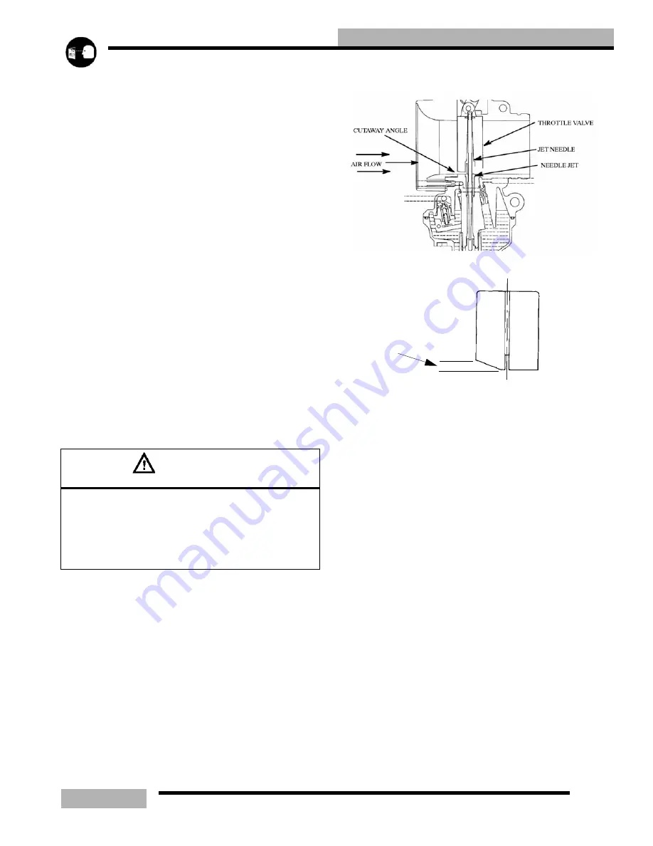
PISTON VALVE or THROTTLE VALVE
The throttle valve controls the rate of engine air intake by
moving up and down inside the main bore. At small throttle
openings, air flow control is performed chiefly by the cutaway.
By controlling air flow the negative pressure over the needle
valve is regulated, in turn varying the fuel flow.
The throttle valves are numbered 1.0, 1.5, 2.0, etc., according
to the size of the cutaway in millimeters. The higher the
number, the leaner the gasoline/air mixture.
JET NEEDLE / NEEDLE JET
The jet needle and needle jet have the most effect between 3/8
and 3/4 throttle opening. Some mixture adjustment can be
accomplished by changing the location of the E" clip on the
needle. Moving the clip down raises the needle in the jet
passage and richens the mixture. Moving the clip up lowers
the needle in the jet passage and leans the mixture. Letter and
number codes are stamped into the needle and the jet
indicating sizes and tapers (taper of needles only) of each.
JET NEEDLE
The jet needle tapers off at one end and the clearance between
the jet needle and the needle jet increases as the throttle valve
opening gets wider. The air/fuel mixture ratio is controlled by
the height of the “E" ring inserted into one of the five slots
CAUTION
A Main Jet that is too small will cause a lean operation
condition and may cause serious engine damage. jet
the carburetors carefully for elevation and temperature
according to the jetting charts in the Specifications
Chapter of this manual or the models Owners Manual
Supplements
intake side
Summary of Contents for SUPERSPORT 2006
Page 48: ...NOTES SPECIFICATIONS 1 48...
Page 55: ...2 7 GENERAL SAE TAP DRILL SIZES METRIC TAP DRILL SIZES DECMIAL EQUIVALENTS...
Page 60: ...2 12 GENERAL SPECIAL TOOLS...
Page 61: ...2 13 GENERAL...
Page 62: ...2 14 GENERAL...
Page 106: ...4 18 CARBURETION...
Page 139: ...6 27 ENGINE 340 550 ENGINE REBUILDING 10 11 3 4 12 13 5 2 14 1 16 15 16 9 17 6 7 8...
Page 156: ...7 12 CLUTCHING 1 1 2 3 4 5 6 7 18 17 10 8 9 13 12 11 15 16 14...
Page 192: ...8 20 FINAL DRIVE...
Page 200: ...10 2 FRONT SUSPENSION STEERING FUSION IQ RMK 600 RMK Fusion 14 78...
Page 201: ...10 3 FRONT SUSPENSION STEERING EDGE RMK Apply Polaris All Season Grease to all zerks...
Page 202: ...10 4 FRONT SUSPENSION STEERING 42 5 EDGE Apply Polaris All Season Grease to all zerks...
Page 203: ...10 5 FRONT SUSPENSION STEERING WIDETRAK Apply Polaris All Season Grease to all zerks...
Page 244: ...11 28 REAR SUSPENSION...
Page 256: ...12 12 CHASSIS HOOD...
Page 282: ...13 26 ELECTRICAL...
Page 288: ...13 32 ELECTRICAL...
Page 289: ...14 1 WIRE DIAGRAM 2006 600 FUSION HO HOOD...
Page 290: ...14 2 WIRE DIAGRAM 2006 HO RMK HOOD...
Page 291: ...14 3 WIRE DIAGRAM 600 HO FUSION RMK CHASSIS...
Page 292: ...14 4 WIRE DIAGRAM 600 HO FUSION RMK CHASSIS CALL OUTS...
Page 293: ...14 5 WIRE DIAGRAM 700 900 ENGINE...
Page 294: ...14 6 WIRE DIAGRAM 700 900 ENGINE AND ENGINE CALL OUTS...
Page 295: ...14 7 WIRE DIAGRAM 700 900 CHASSIS...
Page 297: ...14 9 WIRE DIAGRAM 340 550 FUJI FAN ENGINE CHASSIS...
Page 298: ...14 10 WIRE DIAGRAM 500 FUJI ENGINE CHASSIS...
Page 299: ...14 11 WIRE DIAGRAM 500 600 IBERTY ENGINE CHASSIS...


