4.5
CARBURETION
opening. Whether idling or at full throttle, the pressure built up
in the crankcase has enough amplitude to operate the pump.
When the piston is on the upstroke, crankcase pressure in that
cylinder becomes less positive. The diaphragm in the fuel
pump moves toward the engine, causing a negative pressure or
suction in the pump chamber. This causes the inlet valve from
the fuel supply to open and permits fuel to enter the chamber.
This same suction causes the outlet valve (to the carburetor) to
close so that fuel cannot return form the carburetor.
When the piston begins its downward stroke, the pressure
from the crankcase becomes positive, causing the fuel pump
diaphragm to move in the opposite direction and reversing the
pressure in the fuel pump chamber. This causes the inlet valve
in the pump to close and the outlet valve to open, filling the
float bowl in the carburetor. When the float level in the
carburetor reaches its standard level, the needle valve will
close, preventing more fuel from entering the carburetor, even
though the fuel pump continues to try to provide the carburetor
with fuel.
MAINTENANCE
The impulse operated diaphragm fuel pump does not require
any specific scheduled maintenance. However, the following
procedures should be observed.
OPERATION
The pump may be checked for operation by removing the fuel
supply line from the carburetor and placing it into a container.
With the engine idling at approximately 2000 RPM, a steady
flow of fuel should be visible.
CLEANING
The pump and impulse line must be disassembled and cleaned
of foreign material in the event of piston or other internal
engine part failures which produce fragments.
INSPECTION
Disconnect impulse line from pump. Connect a Mity Vac to
impulse fitting (or line) and apply 4-6 PSI pressure.
Diaphragm should hold pressure indefinitely.
The diaphragms and check valves must be carefully examined
for cracks, holes, or other damage. If in doubt as to the
condition of any internal parts, replace all diaphragms, check
valves, and gaskets.
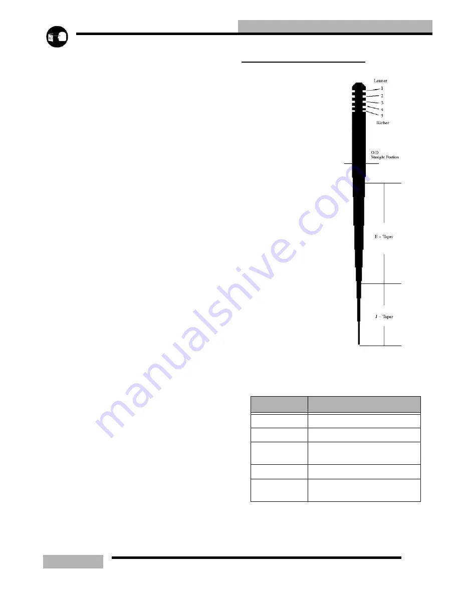
MIKUNI JET NEEDLE
OVERVIEW
This needle (example) is a
9DH01-57. The first number
is the approximate overall
length in 10mm increments of
the jet needle. The 9 indicates
the needle is approximately
90mm but less that 100mm in
length.
The letters on the jet needle
indicate the angle of both
tapers. The first letter
designates the taper angle of
the top section (closest to the
grooves) and the second letter
designates the angle of the
bottom taper. The taper
angles are graduated in 15'
(15 minute) increments. The
jet needle marked 9DH01-57
would have a top taper of 1
_
0'
and a bottom taper of 2
_
0'.
The number following the
letters on the jet needle is the
serial number and it varies
with individual jet needles.
The last number, 57 indicates
that the outside diameter is
2.57mm. The smaller the O.D., the richer the mixture.
Table 4-1: Mikuni Jet Needle
DESIGNATOR
DESCRIPTION
9
Overall length in 10mm increments
D
Taper of the
top
section of the needle
H
taper of the
bottom
section of the
needle
01
Serial number
-57
Outside diameter (O.D.) of the
straight portion
Summary of Contents for SUPERSPORT 2006
Page 48: ...NOTES SPECIFICATIONS 1 48...
Page 55: ...2 7 GENERAL SAE TAP DRILL SIZES METRIC TAP DRILL SIZES DECMIAL EQUIVALENTS...
Page 60: ...2 12 GENERAL SPECIAL TOOLS...
Page 61: ...2 13 GENERAL...
Page 62: ...2 14 GENERAL...
Page 106: ...4 18 CARBURETION...
Page 139: ...6 27 ENGINE 340 550 ENGINE REBUILDING 10 11 3 4 12 13 5 2 14 1 16 15 16 9 17 6 7 8...
Page 156: ...7 12 CLUTCHING 1 1 2 3 4 5 6 7 18 17 10 8 9 13 12 11 15 16 14...
Page 192: ...8 20 FINAL DRIVE...
Page 200: ...10 2 FRONT SUSPENSION STEERING FUSION IQ RMK 600 RMK Fusion 14 78...
Page 201: ...10 3 FRONT SUSPENSION STEERING EDGE RMK Apply Polaris All Season Grease to all zerks...
Page 202: ...10 4 FRONT SUSPENSION STEERING 42 5 EDGE Apply Polaris All Season Grease to all zerks...
Page 203: ...10 5 FRONT SUSPENSION STEERING WIDETRAK Apply Polaris All Season Grease to all zerks...
Page 244: ...11 28 REAR SUSPENSION...
Page 256: ...12 12 CHASSIS HOOD...
Page 282: ...13 26 ELECTRICAL...
Page 288: ...13 32 ELECTRICAL...
Page 289: ...14 1 WIRE DIAGRAM 2006 600 FUSION HO HOOD...
Page 290: ...14 2 WIRE DIAGRAM 2006 HO RMK HOOD...
Page 291: ...14 3 WIRE DIAGRAM 600 HO FUSION RMK CHASSIS...
Page 292: ...14 4 WIRE DIAGRAM 600 HO FUSION RMK CHASSIS CALL OUTS...
Page 293: ...14 5 WIRE DIAGRAM 700 900 ENGINE...
Page 294: ...14 6 WIRE DIAGRAM 700 900 ENGINE AND ENGINE CALL OUTS...
Page 295: ...14 7 WIRE DIAGRAM 700 900 CHASSIS...
Page 297: ...14 9 WIRE DIAGRAM 340 550 FUJI FAN ENGINE CHASSIS...
Page 298: ...14 10 WIRE DIAGRAM 500 FUJI ENGINE CHASSIS...
Page 299: ...14 11 WIRE DIAGRAM 500 600 IBERTY ENGINE CHASSIS...


