3.10
MAINTENANCE
MAIN BEARING
Clean crankshaft thoroughly and oil main and connecting rod
bearings with Polaris engine oil. Carefully check each main
bearing on the shaft.
Due to extremely close tolerances, the bearings must be
inspected visually, and by feel. Look for signs of
discoloration, scoring or galling. Turn the outer race of each
bearing. The bearings should turn smoothly and quietly. The
inner race of each bearing should fit tightly on the crankshaft.
The outer race should be firm with minimal side to side
movement and no detectable up and down movement. Replace
any loose or rough bearings.
CONNECTING ROD (BIG END) BEARING
Specialized equipment and a sound knowledge of crankshaft
repair and straightening is required to perform crankshaft
work safely and correctly. Crankshaft repair should be
performed by trained Polaris service technicians in a properly
equipped shop.
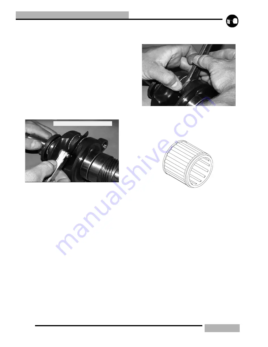
Measure connecting rod big end side clearance with a feeler
gauge. 500/600 Liberty
t
engines should have a clearance of
.011 - .030
"
(.28 -.75mm) and 700/800/900 Liberty
t
engines should have .011 - .028
"
(.28 - .70mm) and be equal
on all rods within .002
"
(.05mm).
Rotate the connecting rod on the crankshaft and feel for any
rough spots. Check radial end play in rod by supporting rod
against one thrust washer and alternately applying up and
down pressure. Replace bearing, pin, and thrust washers if
side clearance is excessive or if there is any up and down
movement detectable in the big end bearing.
WRIST PIN BEARING
1.
Clean the end of the connecting rod and inspect inner bore
with a magnifying glass. Look for any surface
irregularities including pitting, wear, or dents.
2.
Run you fingernail around the inside of the rod and check
for rough spots, galling, or wear.
3.
Oil and install needle bearing and pin in connecting rod.
4.
Rotate pin slowly and check for rough spots or any
resistance to movement.
5.
Slide pin back and forth through bearing while rotating
and check for rough spots.
6.
With pin and bearing centered in rod, twist ends back and
forth in all directions to check for excessive axial play.
7.
Pull up and down evenly on both ends of pin to check for
radial play.
8.
Replace pin and bearing if there is any resistance to
rotation or excessive axial or radial movement. If play or
roughness is evident with a new pin and bearing, replace
the connecting rod.
Within .002” (.05mm)
NEEDLE BEARING
Summary of Contents for SUPERSPORT 2006
Page 48: ...NOTES SPECIFICATIONS 1 48...
Page 55: ...2 7 GENERAL SAE TAP DRILL SIZES METRIC TAP DRILL SIZES DECMIAL EQUIVALENTS...
Page 60: ...2 12 GENERAL SPECIAL TOOLS...
Page 61: ...2 13 GENERAL...
Page 62: ...2 14 GENERAL...
Page 106: ...4 18 CARBURETION...
Page 139: ...6 27 ENGINE 340 550 ENGINE REBUILDING 10 11 3 4 12 13 5 2 14 1 16 15 16 9 17 6 7 8...
Page 156: ...7 12 CLUTCHING 1 1 2 3 4 5 6 7 18 17 10 8 9 13 12 11 15 16 14...
Page 192: ...8 20 FINAL DRIVE...
Page 200: ...10 2 FRONT SUSPENSION STEERING FUSION IQ RMK 600 RMK Fusion 14 78...
Page 201: ...10 3 FRONT SUSPENSION STEERING EDGE RMK Apply Polaris All Season Grease to all zerks...
Page 202: ...10 4 FRONT SUSPENSION STEERING 42 5 EDGE Apply Polaris All Season Grease to all zerks...
Page 203: ...10 5 FRONT SUSPENSION STEERING WIDETRAK Apply Polaris All Season Grease to all zerks...
Page 244: ...11 28 REAR SUSPENSION...
Page 256: ...12 12 CHASSIS HOOD...
Page 282: ...13 26 ELECTRICAL...
Page 288: ...13 32 ELECTRICAL...
Page 289: ...14 1 WIRE DIAGRAM 2006 600 FUSION HO HOOD...
Page 290: ...14 2 WIRE DIAGRAM 2006 HO RMK HOOD...
Page 291: ...14 3 WIRE DIAGRAM 600 HO FUSION RMK CHASSIS...
Page 292: ...14 4 WIRE DIAGRAM 600 HO FUSION RMK CHASSIS CALL OUTS...
Page 293: ...14 5 WIRE DIAGRAM 700 900 ENGINE...
Page 294: ...14 6 WIRE DIAGRAM 700 900 ENGINE AND ENGINE CALL OUTS...
Page 295: ...14 7 WIRE DIAGRAM 700 900 CHASSIS...
Page 297: ...14 9 WIRE DIAGRAM 340 550 FUJI FAN ENGINE CHASSIS...
Page 298: ...14 10 WIRE DIAGRAM 500 FUJI ENGINE CHASSIS...
Page 299: ...14 11 WIRE DIAGRAM 500 600 IBERTY ENGINE CHASSIS...


