background image

2

2.39

9924864 - 2012-2014 SPORTSMAN 800 / 6X6

© Copyright 2013 Polaris Sales Inc.

Tire Pressure

CAUTION

Maintain proper tire pressure. Refer to the warning tire

pressure decal applied to the vehicle.

TIRE PRESSURE INSPECTION (PSI - COLD) 4X4

Front

Rear

5 (34.5 Kpa)

5 (34.5 Kpa)

TIRE PRESSURE INSPECTION (PSI - COLD) 6X6

Front

Rear

7 (48.25 Kpa)

10 (69 Kpa)

Tire Inspection

• Improper

tire

inflation

may

affect

ATV

maneuverability.

• When

replacing

a

tire

always

use

original

equipment size and type.

• The use of non-standard size or type tires may

affect ATV handling.

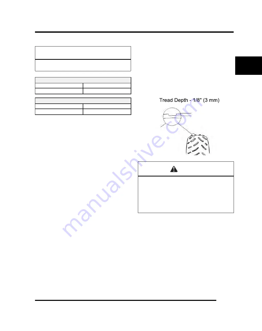
Tire Tread Depth

Always replace tires when tread depth is worn to 1/8, (3
mm) or less.

WARNING

Operating an ATV with worn tires will increase the

possibility of the vehicle skidding and possible loss of

control.

Worn tires can cause an accident.

Always replace tires when the tread depth measures 1/

8inch (.3 cm) or less.

MAINTENANCE

Summary of Contents for Sportsman 800 EFI 4x4 2012

Page 1: ... correctly Technicians should read the text and be familiar with the service procedures before starting any repair Certain procedures require the use of special tools Use only the proper tools as specified If you have any doubt as to your ability to perform any of the procedures outlined in this Service Manual contact an authorized dealer for service We value your input and appreciate any assistan...

Page 2: ...e or in part is expressly prohibited Printed in U S A UNDERSTANDING SAFETY LABELS AND DIRECTIONS Throughout this manual important information is brought to your attention by the following symbols WARNING SAFETY ALERT WARNING indicates a potential hazard that may result in severe injury or death to the operator bystander or person s inspecting or servicing the vehicle CAUTION SAFETY ALERT CAUTION i...

Page 3: ...ty Vac Registered Trademark of Neward Enterprises Inc Torx Registered Trademark of Textron Hilliard Trademark of the Hilliard Corporation Warn Trademark of Warn Industries FOX Registered Trademark of FOX RACING SHOX RydeFX Registered Trademark of ArvinMeritor Some Polaris factory publications can be downloaded from www polarisindustries com purchased from www purepolaris com or by contacting the n...

Page 4: ......

Page 5: ...1 GENERAL INFORMATION 2 MAINTENANCE 3 ENGINE 4 FUEL SYSTEM GENERAL 5 BODY STEERING SUSPENSION 6 CLUTCHING 7 FINAL DRIVE 8 TRANSMISSION 9 BRAKES 10 ELECTRICAL ...

Page 6: ......

Page 7: ... SERIAL NUMBER LOCATION 1 4 SPORTSMAN 800 EFI 4X4 SPECIFICATIONS 1 5 2012 2014 SPORTSMAN 800 EFI 1 5 SPORTSMAN 800 EFI BIG BOSS 6X6 SPECIFICATIONS 1 7 2012 2014 SPORTSMAN 800 EFI BIG BOSS 6X6 1 7 PUBLICATIONS PAINT CODES KEYS TOOLS 1 9 PUBLICATIONS 1 9 PAINT CODES 1 9 SPECIAL TOOLS 1 10 REPLACEMENT KEYS 1 10 MISC NUMBERS CHARTS 1 11 CONVERSION TABLE 1 11 SAE TAP DRILL SIZES 1 12 METRIC TAP DRILL S...

Page 8: ...rsions of models not including the base First 3 digits and 9th digit are used in model number only They are not used with the 17 digit VIN Digits 1 through 8 determine Digital Wrench calibration Vehicle Identification Number VIN Designation Example 4XAKA09A0E3000000 WORLD MFG ID VEHICLE DESCRIPTORS VEHICLE IDENTIFIERS CH AS SIS DRI VE LIN E EN GI NE SIZ E EN GI NE MO DI FIE R CA TE GO RY CH EC K D...

Page 9: ...al number are important for identification purposes Whenever corresponding about a Polaris utility vehicle be sure to refer to the VIN and the engine serial number The machine VIN is stamped on the lower left side of the frame tube A The engine serial number can be found on the sticker applied to the side of the cylinder head B An additional identification number is stamped on the side of the cran...

Page 10: ...ission Serial Number Location The transmission serial number is important for identification purposes Whenever corresponding about a transmission be sure to refer to the transmission serial number The transmission ID is printed on a label located as shown below GENERAL INFORMATION ...

Page 11: ... 760cc Number of Cylinders 2 Bore Stroke mm 80 x 76 5 mm Compression Ratio 11 1 Compression Pressure 150 200 psi Engine Idle Speed 1150 100 RPM Engine Max Operating Rpm 6600 Rpm 200 Rpm Cooling System Capacity Liquid 3 6 qt 3 4 ltr Overheat Warning HOTon Instrument Cluster Lubrication Pressurized Wet Sump Oil Requirements Capacity Polaris 2W 50 2 qt 1 9 liters Exhaust System Single Pipe Silencer F...

Page 12: ...rut Front Travel 8 2 in 21 cm Rear Suspension Shock Progressive Rate Independent Coil over shock Rear Travel 9 5 in 24 13 cm Ground Clearance 11 25 in 28 6 cm Shock Preload Adjustment Front Rear Front Non Adjustable Rear Ratchet Style Std Turning Radius 76 in 193 cm Toe Out 0 1 16 in 0 159 mm Wheels Brakes Front Tire Size 25 x 8 12 Rear Tire Size 25 x 11 12 Tire Pressure F R 5 psi 34 5 Kpa Brake F...

Page 13: ...gth 112 in 284 40 cm Width 48 in 116 8 cm Height 48 in 119 4 cm Seat Height 34 in 86 4 cm Wheel Base 79 5 in 201 93 cm CATEGORY DIMENSION CAPACITY Dry Weight 1060 lbs 480 80 kg Front Rack Capacity 100 lbs 45 4 kg Rear Box Capacity 800 lbs 362 87 kg Towing Capacity 1500 lbs 680 kg Unbraked Trailer Towing Capacity EU 2127 5 lbs 965 kg Hitch Tongue Capacity 150 lbs 68 kg Combination of rear box and t...

Page 14: ...on Timing 13 BTDC 1200 RPM Spark plug Gap RC7YC3 035 in 0 9 mm Battery Amp Hr Lead Acid 30 Amp Hr Circuit Breakers Fan 20 amp Harness 20 amp ECU 15 amp Inst Cluster Voltage Regulator 6 amp DRIVETRAIN Transmission Type Drumshift H L N Rev Park Transmission Capacity 17 2 oz 510 ml Front Gearcase Capacity ADC 9 3 oz 275 ml Mid Gearcase Capacity 13 5 oz 400 ml Rear Gearcase Capacity 5 oz 150ml Gear Ra...

Page 15: ...408 FF 9923405 AA 9923409 FF 2013 Sportsman 800 EFI 4x4 A13MH76AX AZ FF 9923794 AX AZ 9923936 FF 9923795 AX AZ 9923937 FF 2013 Sportsman 800 EFI Big Boss 6x6 A13CF76AA FF 9923797 AA 9923929 FF 9923798 AA 9923930 FF 2014 Sportsman 800 EFI 4x4 A14MH76AA AH FD 9924248 AA 9924248 AH 9924421 FD 9924643 AA 9924643 AH 9924644 FD 2014 Sportsman 800 EFI Big Boss 6x6 A14CF76AA FA 9924249 AA 9924416 FA 99246...

Page 16: ...ols through Polaris official tool supplier Bosch Automotive Service Solutions 1 800 345 2233 or on line at http polaris service solutions com Replacement Keys Replacement keys can be made from the original key To identify which series the key is take the first two digits on the original key and refer to the chart to the right for the proper part number Should both keys become lost ignition switch ...

Page 17: ...mile mi x 1 6 km km x 0 6214 mile ounces oz x 28 35 grams g fluid ounces fl oz x 29 57 cubic centimeters cc cubic centimeters cc x 03381 fluid ounces grams g x 0 035 ounces pounds lb x 0 454 kg kilogram kg x 2 2046 lbs cubic inches cu in x 16 387 cc cubic centimeters cc x 0 061 cubic inches US quarts x 0 946 liters L liters L x 1 057 US quarts US gallons x 3 785 liters L liters L x 0 264 US gallon...

Page 18: ... 12 1 27 64 12 28 4 6 mm 1 3 4 5 1 9 16 1 4 20 7 1 3 4 12 1 43 64 1 4 28 3 2 4 1 2 1 25 32 5 16 18 F 2 12 1 59 64 5 16 24 I 2 1 4 4 1 2 2 1 32 3 8 16 O 2 1 2 4 2 1 4 3 8 24 Q 2 3 4 4 2 1 2 7 16 14 U 3 4 2 3 4 7 16 20 25 64 Metric Tap Drill Sizes TAP SIZE DRILL SIZE DECIMAL NEAREST FRACTION 3 x 50 39 0 0995 3 32 3 x 60 3 32 0 0937 3 32 4 x 70 30 0 1285 1 8 4 x 75 1 8 0 125 1 8 5 x 80 19 0 166 11 64...

Page 19: ...16 20 35 48 55 76 80 110 1 2 13 50 69 75 104 110 152 1 2 20 55 76 90 124 120 166 Metric Bolt Torque Specification BOLT SIZE GRADE 4 6 4 8 8 8 8 9 10 9 12 9 FT LBS NM DRY THREADS M3 3 5 5 7 1 1 3 1 5 2 1 5 2 M4 8 1 1 1 1 5 2 3 3 4 5 4 5 M5 1 5 2 5 2 3 4 5 6 6 5 9 7 5 10 M6 3 4 4 5 5 7 5 10 11 15 13 18 M8 7 9 5 10 13 18 25 26 35 33 45 M10 14 19 18 25 37 50 55 75 63 85 M12 26 35 33 45 63 85 97 130 11...

Page 20: ...m 0 3937 13 32 0 4063 27 64 0 4219 11 mm 0 4331 7 16 0 4375 29 64 0 4531 15 32 0 4688 12 mm 0 4724 31 64 0 4844 1 2 0 500 13 mm 0 5118 33 64 0 5156 17 32 0 5313 35 64 0 5469 14 mm 0 5512 9 16 0 5625 37 64 0 5781 15 mm 0 5906 19 32 0 5938 39 64 0 6094 5 8 0 625 16 mm 0 6299 FRACTION DECIMAL MM TO INCHES 41 64 0 6406 21 32 0 6563 17 mm 0 6693 43 64 0 6719 11 16 0 6875 45 64 0 7031 18 mm 0 7087 23 32...

Page 21: ...14 TRANSMISSION LUBRICATION 4X4 2 15 TRANSMISSION LUBRICATION 6X6 2 16 MIDDLE GEARCASE LUBRICATION 6X6 2 17 REAR GEARCASE LUBRICATION 6X6 2 18 VEHICLE INSPECTION 2 19 SHIFT LINK ROD INSPECTION 4X4 2 19 SHIFT LINK ROD INSPECTION 6X6 2 19 THROTTLE INSPECTION 2 19 THROTTLE CABLE THROTTLE RELEASE SYSTEM TRS SWITCH ADJUSTMENT 2 20 FUEL SYSTEM 2 20 VENT LINES 2 20 COMPRESSION TEST 2 21 ENGINE MOUNTS 2 2...

Page 22: ... SYSTEM INSPECTION 2 34 BRAKE PADS 2 35 BRAKE HOSE INSPECTION 2 35 AUXILIARY BRAKE TESTING 2 35 AUXILIARY BRAKE ADJUSTMENT 2 36 SUSPENSION SPRING PRELOAD ADJUSTMENT 2 36 FRONT SUSPENSION 2 36 REAR SUSPENSION 2 36 CV SHAFT BOOT INSPECTION 2 37 ATV CONTROLS 2 37 WHEEL INSPECTION 2 37 FRAME NUTS BOLTS FASTENERS 2 38 WHEEL REMOVAL FRONT OR REAR 2 38 WHEEL INSTALLATION 2 38 TIRE PRESSURE 2 39 TIRE INSP...

Page 23: ...eed heavy load operation Extended idle Short trip cold weather operation Pay special attention to the oil level A rise in oil level during cold weather can indicate contaminants collecting in the oil sump or crankcase Change oil immediately if the oil level begins to rise Monitor the oil level and if it continues to rise discontinue use and determine the cause Maintenance Chart Key The following s...

Page 24: ... clean often E Air Box Sediment Tube Daily Drain deposits when visible Coolant if applicable Daily Check level daily change coolant every 2 years Head lamp tail lamp Daily Check operation apply dielectric grease if replacing E Air filter main element Weekly Inspect replace as needed Recoil housing if applicable Weekly Drain water as needed check often if operating in wet conditions E Brake Pad Wea...

Page 25: ... Cable TRS Switch 50 H 6 M 500 800 Inspect adjust lubricate replace if necessary E Air intake ducts 50 H 6 M 500 800 Inspect ducts for proper sealing air leaks Drive belt 50 H 6 M 500 800 Inspect adjust replace as needed Cooling system if applicable 50 H 6 M 500 800 Inspect coolant strength seasonally pressure test system yearly E Engine Oil Change 100 H 6 M 1000 1600 Perform a break in oil change...

Page 26: ...pect for wear routing security apply dielectric grease to connectors subjected to water mud etc Clutches drive driven 100 H 12 M 1000 1600 Inspect clean replace worn parts Front wheel bearings 100 H 12 M 1000 1600 Inspect replace as needed Brake fluid 200 H 24 M 2000 3200 Change every two years ADC fluid 200 H 24 M 2000 3200 Change every two years Spark arrestor 300 H 36 M 3000 4800 Clean out E Id...

Page 27: ...al 2 Count 2877922 Demand Drive Fluid Quart 2877923 Demand Drive Fluid 2 5 Gallon 2870465 Oil Pump for 1 Gallon Jug Grease Specialized Lubricants 2871312 Grease Gun Kit 2871322 Premium All Season Grease 3 oz cartridge 24 Count 2871423 Premium All Season Grease 14 oz cartridge 10 Count 2871460 Starter Drive Grease 12 Count 2871515 Premium U Joint Lube 3 oz 24 Count 2871551 Premium U Joint Lube 14 o...

Page 28: ...ons or short trip cold weather operation 2 Transmission Polaris AGL Synthetic Gearcase Lube Add lube to bottom fill hole Change annually B 3 Front Gearcase Demand Drive Fluid Drain as directed Add specified quantity Gearcase Change annually B 4 Brake Fluid Polaris DOT 4 Brake Fluid Fill master cylinder reservoir to indicated level As required change fluid every 2 years 5 Front A Arm Polaris All Se...

Page 29: ... fluid every 2 years 6 Front A Arm Polaris All Season Grease Locate fitting and grease Semi annually A 7 Rear A Arm Polaris All Season Grease Locate fitting and grease Semi annually A 8 Front Propshaft Polaris U Joint Grease C Locate fitting and grease Semi annually A Perform more often under severe use such as operation in water and under severe loads A Semi annually or 50 hours of operation Refe...

Page 30: ...tain the dipstick is inserted all the way into the filler tube to keep the angle and depth of stick consistent When reinstalling the dipstick make certain to seat the lever lock 6 Remove dipstick C and check to see that the oil level is in the normal range Add oil as indicated by the level on the dipstick Do not overfill See NOTE below NOTE Due to the dipstick entry angle into the crankcase the oi...

Page 31: ...unterclockwise to remove 9 Using a clean dry cloth clean filter sealing surface on crankcase 10 Lubricate O ring on new filter with a film of fresh engine oil Check to make sure the O ring is in good condition 11 Install new filter and turn by hand until filter gasket contacts the sealing surface then turn an additional 1 2 turn 12 Remove dipstick and fill sump with 2 quarts 1 9 l of recommended e...

Page 32: ...g 8 30 ft lbs 11 40 Nm Drain Plug 8 30 ft lbs 11 40 Nm To Check the Lubricant Level Remove the check fill plug The fluid level should be at the bottom of the check fill plug case threads See next page To Change Gearcase Lubricant 1 Remove gearcase drain plug A located on the bottom of the gearcase and drain oil The drain plug is accessible through the skid plate Catch and discard used oil properly...

Page 33: ...tant ADC operation on hilly or mountainous terrain or if ADC is the primary mode of operation Fill Plug 8 30 ft lbs 11 40 Nm Drain Plug 8 30 ft lbs 11 40 Nm To Check the Lubricant Level Remove the check fill plug The fluid level should be at the bottom of the check fill plug case threads See next page To Change Gearcase Lubricant 1 Remove gearcase drain plug A located on the bottom of the gearcase...

Page 34: ...egin the bleeding process by filling reservoir to MAX line with clean Demand Drive fluid 6 Locate bleeder valves found on either side of differential and remove the protective caps 7 Turn bleeder valves counter clockwise to loosen Loosen bleeder screw slowly allowing oil and any trapped air to flow out of fitting NOTE Do not allow hydraulic fluid in reservoir to drain below minimum fill line Close...

Page 35: ...eck fill plug A from the left side of transmission and visually inspect the oil level Level is correct when it reaches the bottom of the fill hole threads To Change Lubricant 1 Remove transmission drain plug B to drain the oil Discard used oil properly 2 Clean and reinstall the drain plug Torque to specification Transmission Drain Plug 14 ft lbs 19 Nm 3 Remove fill plug 4 Add the correct amount of...

Page 36: ...rcase Lubricant Gallon 2878068 Quart PN 2878069 Sportsman 6x6 Capacity 17 2 oz 510 ml Transmission Drain Fill Plug 14 ft lbs 19 Nm To Check the Fluid Level Remove fill plug A from the back of the transmission and visually inspect the oil level Level is correct when it reaches the bottom of the fill hole as shown at below To Change Lubricant 1 Remove transmission drain plug B to drain the oil Disca...

Page 37: ...g 15 ft lbs 20 Nm To Check the Lubricant Level Remove the check fill plug The fluid level should be at the bottom of the check fill plug case threads See next page To Change Gearcase Lubricant 1 Remove gearcase drain plug A located on the bottom of the gearcase and drain oil The drain plug is accessible through the skid plate Catch and discard used oil properly 2 Clean and reinstall drain plug A u...

Page 38: ...n Plug 11 ft lbs 15 Nm To Check the Lubricant Level Remove the check fill plug The fluid level should be at the bottom of the check fill plug case threads See next page To Change Gearcase Lubricant 1 Remove gearcase drain plug A located on the bottom of the gearcase and drain oil The drain plug is accessible through the skid plate Catch and discard used oil properly 2 Clean and reinstall drain plu...

Page 39: ...turn freely without binding 1 Place the gear selector in neutral 2 Place shift selector in neutral and set parking brake 3 Loosen lock nut on in line cable adjuster Ill 1 4 Turn handlebars from full right to full left If idle speed increases at any point in the turning range inspect throttle cable routing and condition Adjust cable tension as needed until lock to lock turning can be accomplished w...

Page 40: ...er drain the fuel system when the engine is hot Severe burns may result Do not overfill the tank The tank is at full capacity when the fuel reaches the bottom of the filler neck Leave room for expansion of fuel Never start the engine or let it run in an enclosed area Gasoline powered engine exhaust fumes are poisonous and can cause loss of consciousness and death in a short time Do not smoke or al...

Page 41: ...ally high compression can be caused by carbon deposits in the combustion chamber or worn damaged exhaust cam lobes Inspect camshaft and combustion chamber if compression is abnormally high A cylinder leakdown test is the best indication of engine condition Follow manufacturer s instructions to perform a cylinder leakage test Never use high pressure leakage testers as crankshaft seals may dislodge ...

Page 42: ...act cleaner or a glass bead spark plug cleaner only CAUTION A wire brush or coated abrasive should not be used for cleaning spark plugs 5 Measure gap with a wire gauge Refer to specifications for proper spark plug type and gap Adjust gap if necessary by bending the side electrode carefully 6 If necessary replace spark plug with proper type WARNING Severe engine damage may occur if the incorrect sp...

Page 43: ...rge battery for 3 5 hours at a current equivalent of 1 10 of the battery s rated amp hour capacity Do not use the alternator to charge a new battery Refer to battery video PN 9917987 Conventional Battery Only Inspect the battery fluid level When the electrolyte nears the lower level remove the battery and add distilled water only to the upper level line To Remove the Battery 1 Disconnect holder st...

Page 44: ...d from system Polaris Premium 60 40 anti freeze is premixed and ready to use Do not dilute with water Coolant Strength Type Test the strength of the coolant using an antifreeze hydrometer A 50 50 or 60 40 mixture of antifreeze and distilled water will provide the optimum cooling corrosion protection and antifreeze protection Do not use tap water straight antifreeze or straight water in the system ...

Page 45: ...area 3 Reinstall cap IMPORTANT If overheating is evident allow system to cool completely and check coolant level in the radiator Inspect for signs of trapped air in system Radiator Coolant Level WARNING Never remove the radiator pressure cap when the engine is warm or hot Escaping steam and fluid can cause severe burns The engine must be allowed to cool before removing the pressure cap NOTE This p...

Page 46: ...e pressure cap and inspect fluid level Using a funnel add coolant until the fluid level is to the top of the filler neck 6 Reinstall the pressure cap and install the front access cover Radiator Grill Screen 1 Check radiator air passages for restrictions or damage Check and clean the radiator grille if needed 2 Carefully straighten any bent radiator fins 3 Remove any obstructions with compressed ai...

Page 47: ...d 4 Loosen clamp and remove air filter assembly Cleaning 5 Slip the pre filter element off of main element Clean the pre filter with hot soapy water 6 Rinse and dry thoroughly 7 Inspect element for tears or damage 8 Inspect main filter and replace if necessary If the filter has been soaked with fuel or oil it must be replaced Installation 9 Reinstall pre filter element over main filter Be sure the...

Page 48: ...e B 2 Drain tube 3 Reinstall drain plug NOTE The sediment tube will require more frequent service if the vehicle is operated in wet conditions or at high throttle openings for extended periods Engine Breather Hose Four cycle ATV engines are equipped with a engine breather hose C The breather line is located on top of the cylinder head cover below the gas tank Be sure breather line is routed proper...

Page 49: ...he bottom of the PVT cover and let the water drain out The PVT drain plug is shown below 2 To further expel water from the cover and to dry out the PVT system shift the transmission to neutral and rev engine slightly to expel the moisture and air dry the belt and clutches Allow engine RPM to settle to idle speed shift transmission to lowest available range and test for belt slippage Operate ATV in...

Page 50: ...y for loose fasteners worn tie rod ends and damage Also check to make sure all cotter pins are in place If cotter pins are removed they must not be re used Always use new cotter pins Replace any worn or damaged steering components Steering should move freely through entire range of travel without binding Check routing of all cables hoses and wiring to be sure the steering mechanism is not restrict...

Page 51: ...ront end of machine so front wheels are off the ground Check for any looseness in front hub wheel assembly by grasping the tire firmly at top and bottom first and then at front and rear Try to move the wheel and hub by pushing inward and pulling outward If abnormal movement is detected inspect the hub and wheel assembly to determine the cause possible loose wheel nuts or loose front hub components...

Page 52: ... 3 to 6 cm toe out This means the measurement at the front of the tire A is 1 8 to 1 4 3 to 6 cm wider than the measurement at the rear B Wheel Toe Out A B 1 8 1 4 3 to 6 cm Toe Alignment If toe alignment is incorrect measure the distance between vehicle center and each wheel This will tell you which tie rod needs adjusting NOTE Be sure handlebars are straight ahead before determining which tie ro...

Page 53: ...ilure to heed these warnings could result in serious personal injury or death 1 Remove the clean out plugs located on the bottom of the muffler as shown 2 Place the transmission in neutral and start the engine Purge accumulated carbon from the system by momentarily revving the engine several times 3 If some carbon is expelled cover the exhaust outlet and rap on the pipe around the clean out plugs ...

Page 54: ...rake system in good operating condition Service life of brake system components depends on operating conditions Inspect brakes in accordance with the maintenance schedule and before each ride Keep fluid level in the master cylinder reservoir to the indicated level inside reservoir Use Polaris DOT 4 Brake Fluid Use Polaris DOT 4 Brake Fluid Check brake for excessive travel or spongy feel Check brak...

Page 55: ...fittings for cracks deterioration abrasion and leaks Tighten any loose fittings and replace any worn or damaged parts Auxiliary Brake Testing The auxiliary brake should be checked for proper function 1 Support the rear wheels off the ground 2 While turning the rear wheels by hand apply the auxiliary foot brake This brake should not stop the wheels from turning until the lever is half way between i...

Page 56: ...ay is correct and brake pedal travel is still excessive air may be trapped somewhere in the system Bleed the hydraulic auxiliary brake system in a conventional manner following the procedure outlined in Brake Chapter 9 Suspension Spring Preload Adjustment Operator weight and vehicle loading affect suspension spring preload requirements Adjust as necessary Use Shock Spanner Wrench PN 2870872 to adj...

Page 57: ...ontrols Check controls for proper operation positioning and adjustment Brake control and switch must be positioned to allow brake lever to travel throughout entire range without contacting switch body Wheel Inspection Inspect all wheels for runout or damage Check wheel nuts and ensure they are tight Do not over tighten the wheel nuts ITEM SPECIFICATION Steel Front and Rear Wheel Nuts 27 ft lbs 37 ...

Page 58: ...ission in park and the parking brake locked place the wheel in the correct position on the wheel hub Be sure the valve stem is toward the outside and rotation arrows on the tire point toward forward rotation 2 Attach the wheel nuts and finger tighten them 3 Lower the vehicle to the ground 4 Securely tighten the wheel nuts to the proper torque listed in the table CAUTION Improperly installed wheels...

Page 59: ...Kpa Tire Inspection Improper tire inflation may affect ATV maneuverability When replacing a tire always use original equipment size and type The use of non standard size or type tires may affect ATV handling Tire Tread Depth Always replace tires when tread depth is worn to 1 8 3 mm or less WARNING Operating an ATV with worn tires will increase the possibility of the vehicle skidding and possible l...

Page 60: ...2 40 9924864 2012 2014 SPORTSMAN 800 6X6 Copyright 2013 Polaris Sales Inc NOTES MAINTENANCE ...

Page 61: ... CYLINDER AFTER HONING 3 21 OIL FLOW CHART 3 22 ENGINE LUBRICATION SPECIFICATIONS 3 23 OIL PRESSURE TEST 3 23 ENGINE DISASSEMBLY AND INSPECTION 3 24 CYLINDER HEAD ASSEMBLY EXPLODED VIEW 3 24 ROCKER ARMS 3 25 PUSH RODS 3 25 CYLINDER HEAD REMOVAL 3 26 CYLINDER HEAD INSPECTION 3 26 CYLINDER HEAD WARP 3 26 VALVE SEAL SPRING SERVICE ON ENGINE 3 27 CYLINDER HEAD DISASSEMBLY 3 27 VALVE INSPECTION 3 29 CO...

Page 62: ...ANKCASE DISASSEMBLY INSPECTION 3 42 CAMSHAFT INSPECTION 3 51 ENGINE REASSEMBLY 3 53 CRANKCASE REASSEMBLY 3 53 FLYWHEEL STATOR INSTALLATION 3 66 CYLINDER HEAD INSTALLATION 3 67 800 EFI EXHAUST SYSTEM 3 71 EXHAUST LAYOUT 3 71 TROUBLESHOOTING 3 72 ENGINE 3 72 COOLING SYSTEM 3 73 ENGINE ...

Page 63: ...3 3 3 9924864 2012 2014 SPORTSMAN 800 6X6 Copyright 2013 Polaris Sales Inc SPECIFICATIONS Crankcase Exploded Views ENGINE ...

Page 64: ...3 4 9924864 2012 2014 SPORTSMAN 800 6X6 Copyright 2013 Polaris Sales Inc Oil Water Pump and Timing Cover Exploded View ENGINE ...

Page 65: ...3 3 5 9924864 2012 2014 SPORTSMAN 800 6X6 Copyright 2013 Polaris Sales Inc Starter Flywheel Water Pump Exploded View ENGINE ...

Page 66: ...3 6 9924864 2012 2014 SPORTSMAN 800 6X6 Copyright 2013 Polaris Sales Inc Oil System Level Assembly Exploded View ENGINE ...

Page 67: ...3 3 7 9924864 2012 2014 SPORTSMAN 800 6X6 Copyright 2013 Polaris Sales Inc Cylinder Cylinder Head Exploded View ENGINE ...

Page 68: ...3 8 9924864 2012 2014 SPORTSMAN 800 6X6 Copyright 2013 Polaris Sales Inc Engine Sensors Misc Exploded View ENGINE ...

Page 69: ...3 3 9 9924864 2012 2014 SPORTSMAN 800 6X6 Copyright 2013 Polaris Sales Inc EFI Harness Exploded View ENGINE ...

Page 70: ...3 10 9924864 2012 2014 SPORTSMAN 800 6X6 Copyright 2013 Polaris Sales Inc Engine Fastener Torque Patterns ENGINE ...

Page 71: ...l Baffle Weldment 5 mm 60 6 6 8 0 68 Oil Drain Bolt Crankcase 12 mm 192 24 21 7 2 7 16 21 7 Oil Fill Tube Bolt 5 mm 50 5 5 64 0 56 Oil Filter Pipe Fitting 20 mm 35 4 47 5 5 4 Oil Pick Up 5 mm 60 6 6 8 0 68 Oil Pressure Relief Plug 10 mm 22 2 30 3 Oil Pump Housing Screw 6 mm 84 8 9 50 0 90 Rocker Arm 8 mm 22 2 30 3 Rocker Cover 6 mm 84 8 9 5 0 9 Spark Plug 14 mm 216 24 24 5 2 7 18 2 24 5 2 7 Starte...

Page 72: ...478 88 35 mm Valve Seat Valve Seat Contacting Width Intake 0 0472 0 00787 0 0039 1 20 0 20 0 10mm Valve Seat Contacting Width Exhaust 0 0591 0 00787 0 0039 1 50 0 20 0 10 mm Valve Seat Angle 45 5 0 255 Valve Guide Valve Guide Inner diameter 0 2367 0 00029 6 012 0 007 mm Valve Guide Protrusion Above Head 0 807 0 0039 20 50 0 01 mm Valve Valve Margin Thickness Intake Standard 0 79 20 06 mm Max 0 98 ...

Page 73: ...0075 mm Cylinder to Piston Clearance 0015 00059 040 015mm Lifter Lifter Outer Diameter Standard 0 84245 0 00025 21 39 8 0 00635 mm Lifter Block Bore 0 8438 0 00062 21 4322 0 0157 mm Piston Piston Standard 3 14803 00028 79 960 007 mm Piston Standard Inner Diameter of Piston Pin Bore 0 70902 00012 18 009 0 003 mm Piston Pin Piston Pin Outer Diameter 0 70866 0 70846 18 17 995 mm Piston Pin Standard C...

Page 74: ...0 25mm Oil Ring Limit 15 Leakdown Ring to Groove Clearance Top Ring Standard 0 0024 0 0008 0 060 0 020 mm Top Ring Limit 15 Leakdown Second Ring Standard 0 0028 0 0008 0 070 0 020 mm Second Ring Limit 15 Leakdown Connecting Rod Connecting Rod Small End I D 0 7096 0 70846 18 17 995 mm Connecting Rod Small End Radial Clearance 0 0098 0 00039 0 025 0 010mm Connecting Rod Big End Side Clearance 0 0118...

Page 75: ...ON SUPPORT BLOCK PU 45497 1 CAM GEAR SPRING INSTALLATION KIT PU 45497 2 CAM GEAR TOOTH ALIGNMENT TOOL PU 45498 CAM SPANNER WRENCH PU 45838 GEAR HOLDER PA 44995 WATER PUMP MECHANICAL SEAL INSTALLER PU 45543 UNIVERSAL DRIVER HANDLE PA 45483 MAIN SEAL INSTALLER PU 45658 CRANKSHAFT MAIN SEAL SAVER PA 45401 WATER PUMP SEAL SAVER 2870975 MITY VAC PRESSURE TEST TOOL PU 45778 OIL SYSTEM PRIMING TOOL Bosch...

Page 76: ...ion Use the information below to identify pistons and rings ENGINE MODEL PISTON DIAMETER EH076OLE 80 mm Cooling System Specifications CONDITION APPROXIMATE READING MIN MAX TEMPERATURE Hot light ON 178Ω 190Ω 215 F 108 C Fan Off 296Ω 316Ω 180 F 82 C Fan On 236Ω 251Ω 195 F 91 C System Capacity Refer To Chapter 1 Specifications Radiator Cap Pressure Relief 13 PSI Recommended Coolant Use only high qual...

Page 77: ...Coolant Air Bleeding Procedure Use this procedure when a unit overheats and no apparent leaks in the cooling system are found NOTE If the coolant level is LOW in the radiator or if there are leaks in the system the coolant system will not draw coolant from the reservoir tank 1 Park machine on a flat surface Remove filler cap and top off coolant With the cap removed start and idle machine for 5 10 ...

Page 78: ...Insert a shop towel into the engine intake to prevent dirt from entering the ports 9 Relieve the fuel pressure in the fuel rail refer to Chapter 4 FUEL INJECTION for proper procedure Carefully remove the fuel rail B and injectors 10 Disconnect spark plug high tension leads 11 Remove the crank position sensor E located on the mag cover 12 Remove the air breather line 13 Disconnect the coolant hoses...

Page 79: ...checklist refer to Chapter 2 or the Owner s Manual PVT System 3 Adjust center distance of drive and driven clutch Chapter 6 4 Adjust clutch offset alignment and belt deflection Chapter 6 5 Clean clutch sheaves thoroughly and inspect inlet and outlet ducts for proper routing and sealing Chapter 6 Transmission 6 Inspect transmission operation and adjust linkage if necessary Refer to Chapter 2 and Ch...

Page 80: ...n build up and cause damage to close fitted engine parts 14 Fill fuel tank with unleaded or leaded fuel which has a minimum pump octane number of 87 R M 2 15 Check oil reservoir level indicated on dipstick Add oil if necessary Refer to Chapter 2 Engine Oil Level 16 Drive slowly at first to gradually bring engine up to operating temperature 17 Vary throttle positions Do not operate at sustained idl...

Page 81: ... to check for correct cross hatch NOTE Do not allow cylinder to heat up during honing After honing has been completed inspect cylinder for thinning or peeling If cylinder wear or damage is excessive it will be necessary to replace the cylinder The cylinders are lined with a nicasil coating and are not repairable Hone only enough to de glaze the outer layer of the cylinder bore IMPORTANT Clean the ...

Page 82: ...t At this point the oil is supplied to the main oil galley through a crankcase passage Oil is then diverted three ways from the main oil galley with the first path entering the camshaft bores onto the rear balance shaft journal and then draining back into the crankcase sump The second oil path from the main oil galley feeds the lifter bores and then drains back to the crankcase sump The third oil ...

Page 83: ... 35 55 PSI 5500 RPM Polaris 2W 50 Synthetic Engine at operating temperature Oil Pressure Test 1 Remove blind plug sender from left side of crankcase 2 Insert a 1 4 NPTF oil pressure gauge adaptor into the crankcase and attach the gauge 3 Start engine and allow it to reach operating temperature monitoring gauge indicator NOTE Use only Polaris PS4 2W 50 Synthetic Engine Lubricant Oil Pressure at 550...

Page 84: ...3 24 9924864 2012 2014 SPORTSMAN 800 6X6 Copyright 2013 Polaris Sales Inc ENGINE DISASSEMBLY AND INSPECTION Cylinder Head Assembly Exploded View ENGINE ...

Page 85: ...Push Rods 1 Clean push rods A in a suitable solvent Blow dry push rods with compressed air 2 Use compressed air to confirm the oil passage is clear in the center of the push rod WARNING Always wear safety glasses when working with compressed air to prevent personal injury 3 Check the ends of the push rods A for nicks grooves roughness or excessive wear 4 The push rods A can be visually checked for...

Page 86: ...ing the head or cylinder 3 Remove cylinder head B and head gasket C from the cylinder D Cylinder Head Inspection Thoroughly clean cylinder head surface to remove all traces of gasket material and carbon CAUTION Use care not to damage sealing surface Cylinder Head Warp 1 Lay a straight edge A across the surface of the cylinder head B at several different points and measure warp by inserting a feele...

Page 87: ...t top dead center TDC Install the Valve Pressure Hose PU 45652 into the spark plug hole Hook the hose to an air compressor and supply 50 to 100 psi to the hose This will seat the valves during valve spring removal Do not remove air from the hose at anytime until reassembly is completed 2 Using the Valve Spring Compressor PU 45257 compress the valve spring and remove the valve keepers NOTE A small ...

Page 88: ... Valve Spring Free Length Std 1 735 44 069 mm 3 Remove valve guide seals NOTE It is recommended to replace seals whenever the cylinder head is disassembled Hardened cracked or worn valve seals will cause excessive oil consumption and carbon buildup 4 Mark the valves with a white pen Remove the valves from the cylinder head This will ensure that the valves are properly placed during engine reassemb...

Page 89: ...end of valve stem for flaring pitting wear or damage A 4 Inspect split keeper groove for wear or flaring of the keeper seat area B NOTE The valves can be re faced or end ground if necessary They must be replaced if extensively worn burnt bent or damaged 5 Measure diameter of valve stem with a micrometer in three places then rotate 90 degrees and measure again six measurements total Compare to spec...

Page 90: ...lean the bottom of the cylinder head Extensive damage to the cylinder head may result Wear safety glasses during cleaning Valve Seat Reconditioning NOTE Polaris recommends that the work be done by a local machine shop that specializes in this area The cylinder head valve guides cannot be replaced WARNING Wear eye protection or a face shield during cylinder head disassembly and reassembly Valve Sea...

Page 91: ...ght cut 4 Inspect the cut area of the seat If the contact area is less than 75 of the circumference of the seat rotate the pilot 180 and make another light cut If the cutter now contacts the uncut portion of the seat check the pilot Look for burrs nicks or runout If the pilot is bent it must be replaced If the contact area of the cutter is in the same place the valve guide is distorted from improp...

Page 92: ...eat If the seat is too narrow widen using the 45 cutter and re check contact point on the valve face and seat width after each cut NOTE When using an interference angle the seat contact point on the valve will be very narrow and is a normal condition Look for an even and continuous contact point all the way around the valve face B Valve Seat Width Intake Std 028 7 mm Limit 055 1 4 mm Exhaust Std 0...

Page 93: ...12 Thoroughly clean cylinder head and valves Cylinder Head Reassembly NOTE Assemble the valves one at a time to maintain proper order 1 Apply engine oil to valve guides and seats 2 Coat valve stem with molybdenum disulfide grease or 2W 50 Synthetic oil 3 Install valve carefully with a rotating motion to avoid damaging valve seal 4 Valve seals should be installed after the valves are in the head to...

Page 94: ...spring more than necessary to install the keepers Valve Sealing Test 1 Clean and dry the combustion chamber area A 2 Pour a small amount of clean solvent onto the intake port and check for leakage around each intake valve The valve seats should hold fluid with no seepage 3 Repeat for exhaust valves by pouring fluid into exhaust port Cylinder Removal 1 Follow engine disassembly procedures to remove...

Page 95: ...fters with a white pen if using the lifters for reassembly This will ensure that the lifters are properly placed during engine reassembly 4 Check the lifters for wear or scores 5 Check the bottom end of lifter to make sure that it has a slight convex 6 If the bottom surface has worn flat it may be used with the original camshaft only IMPORTANT Lifters that are scored worn or if the bottom is not s...

Page 96: ...rings The ring may lose radial tension 3 Remove top compression ring Using a piston ring pliers Carefully expand ring and lift it off the piston CAUTION Do not expand the ring more than the amount necessary to remove it from the piston or the ring may break By hand Placing both thumbs as shown spread the ring open and push up on the opposite side Do not scratch the ring lands 4 Repeat procedure fo...

Page 97: ...ylinder Inspection 1 Remove all gasket material from the cylinder sealing surfaces 2 Inspect the top of the cylinder B for warp using a straight edge A and feeler gauge C Refer to Ill 1 and Ill 2 Cylinder Warp 004 0 1 mm Max 3 Inspect cylinder for wear scratches or damage ENGINE ...

Page 98: ... 2 up from bottom Record measurements If cylinder is tapered or out of round beyond 002 the cylinder must be replaced Cylinder Taper Limit 002 9 05mm Max Cylinder Out of Round Limit 002 0 mm Max 800 Standard Bore Size Both Cylinders 3 1496 80 mm Piston To Cylinder Clearance Measure piston outside diameter at a point 5 mm up from the bottom of the piston at a right angle to the direction of the pis...

Page 99: ...asuring with a thickness gauge Replace piston and rings if ring to groove clearance exceeds service limits Piston Ring Installed Gap 1 Place each piston ring A inside cylinder B using piston to push ring squarely into place as shown See next page NOTE Ring should be installed with the mark facing upward 2 Measure installed gap with a feeler gauge C at both the top and bottom of the cylinder REMIND...

Page 100: ...rter Drive Bendix Removal Inspection 1 Remove stator housing bolts and remove housing 2 Remove the flywheel nut and washer Install Flywheel Puller PN 2871043 and remove flywheel NOTE Do not thread the puller bolts into the flywheel more than 1 4 or stator coils may be damaged 3 Remove starter bendix assembly Note the thrust washers located on both sides of the bendix 4 Inspect the thrust washer fo...

Page 101: ... PN 2871043 and remove flywheel A CAUTION Do not thread the puller bolts into the flywheel more than 1 4 or stator coils may be damaged 4 Use caution when removing the wire hold down B and the stator assembly C Do not tap or bump the gear stator housing cover or the stator This could cause the seal around the gear stator housing cover and the crankcase to break causing a leak 5 Remove the bendix D...

Page 102: ... impeller E Remove part of the water pump seal behind the impeller 3 Remove flywheel nut and washer 4 Install Flywheel Puller PN 2871043 and remove flywheel F CAUTION Do not thread the puller bolts into the flywheel more than 1 4 or stator coils may be damaged 5 Remove the starter bendix G wire holddown plate H and the woodruff key I from the crankshaft The stator does not have to be removed at th...

Page 103: ...nd timing during reassembly of the gears NOTE If replacing one of the gears it is recommended that all of the gears be replaced A gear kit is available in the parts book 9 Use the Cam Gear Tooth Alignment Tool PU 45497 2 O to align the cam split gear assembly With the split gear aligned remove the bolt and cam gear assembly NOTE Install the Cam Gear Tooth Alignment Tool PU 45497 2 into the assembl...

Page 104: ...ead screwdriver between the two gears Remove the top gear The springs should stay in place CAUTION Wear safety glasses at all times Use caution when working with the top gear The springs could cause injury or become lost should they pop out 12 Remove all three springs using one of the tapered pins from the Tapered Pins PU 45497 1 13 With a white marking pen accent the timing mark on the gear that ...

Page 105: ...st flush with the spring Perform this procedure with all three tapered pins Do not push the pins too far through or the springs will pop out NOTE Do not remove the tapered pins at this time 17 Note in the photograph that the Tapered Pins PU 45497 1 are below flush with end of the springs This helps to align the three gear tabs during the next step Cam Gear Spring Installation Tool Kit PU 45497 Tap...

Page 106: ...ter clockwise from the timing mark For ease of installing the Cam Gear Alignment Tool PU 45497 2 R use a twisting motion when pushing down on the tool 21 To remove the balance shaft gear the flat side of the camshaft P must face the balance shaft gear To rotate the camshaft use the Cam Spanner Wrench PU 45498 to rotate the camshaft so the flat side of the camshaft faces the balance shaft gear NOTE...

Page 107: ... crankshaft gear is damaged remove the crankshaft gear with the Flywheel Puller PN 2871043 24 Install the two puller bolts R Tighten the puller bolts up so that the bolts are at equal length 25 Install the Flywheel Puller PN 2871043 and remove the crankshaft gear if needed 26 Rotate the water oil pump gear S so that all four bolts are visible though the gear Remove the four bolts with a hex wrench...

Page 108: ...between the two rotors Measure the gap between the two rotor tips as shown below The clearance should not exceed 0 006 0 15 mm 29 Remove the oil pressure relief The oil pressure relief consists of a bolt washer spring and valve dowel Inspect the valve dowel for signs of possible obstructions Use compressed air to blow out any debris 30 Reinstall the valve dowel chamfered end first Install the spri...

Page 109: ...hing and eyewear are required 32 Remove the snap ring from the assembly Place the housing in a support and press out the bearing shaft assembly 33 Place the shaft in a press to remove the bearing Discard original bearing 34 Press shaft into the new bearing 35 Press the bearing shaft assembly using the bearing s outer race Do not use the shaft to press the assembly into the housing as bearing damag...

Page 110: ...lts Tap on the reinforced areas on the cases using soft hammer Carefully separate the two crankcase halves IMPORTANT Only remove the oil baffle if the baffle is damaged When removing the oil baffle bolts use a heat gun to heat the bolts and loosen the Loctite This will prevent any possible damage to the bolts or to the crankcase casting 39 Remove and clean oil pick up V and oil baffle weldment W E...

Page 111: ...to replace the bearings anytime the engine is disassembled NOTE Plain bearing clearances may be checked using a commercially available plasti gauge material Camshaft Inspection 1 Thoroughly clean the cam shaft 2 Visually inspect each cam lobe for wear chafing or damage 3 Measure height of each cam lobe using a micrometer Compare to specification Cam Lobe Height Intake Exhaust Std 1 3334 33 8674 mm...

Page 112: ...ores Camshaft Journal Bore I D Mag 1 656 0 00039 42 07 0 010 mm Ctr 1 637 0 00039 41 58 0 010 mm PTO 1 617 0 00039 41 07 0 010 mm 6 Calculate oil clearance by subtracting journal O D s from journal bore I D s Compare to specification Calculated Camshaft Oil Clearance Std 0 0027 070mm Limit 0039 10 mm NOTE Replace camshaft if damaged or if any part is worn past the service limit Replace engine bloc...

Page 113: ... PN 2870585 to remove any debris This will ensure proper sealing when installing bolts 1 Install oil pick up A if removed Torque to specification 2 Install oil baffle weldment B Torque bolts to specification Oil Baffle Weldment Oil Pick Up Bolt 60 6 in lbs 6 8 0 68 Nm 3 Install the balance shaft Inspect balance shaft clearance C in both gearcase halves Rotate balance shaft to ensure that there is ...

Page 114: ...ble the crankcase halves Apply LocTite 242 PN 2871949 to the threads and pipe sealant to the bolt flanges Torque bolts to specification following torque pattern at beginning of this chapter Crankcase Bolt 22 2 ft lbs 30 3 Nm Torque in sequence 8 Lubricate cam lobes A and valve lifters B with Moly Lube Grease 9 Lubricate lifters with engine oil and install in the original order as removed in disass...

Page 115: ...on the piston before installation into the cylinders Set the gaps of the rings evenly 120 apart see illustration 13 Install piston assemblies into cylinder aligning the piston pin holes to ensure proper alignment of the pistons to the connecting rods upon assembly Partially install the piston pins into the pistons NOTE To help align the pistons slide a rod that is close to the same diameter as the...

Page 116: ...nto the connecting rods and push the piston pins through the piston and connecting rods 15 Install the piston pin circlips F The circlip ends should be installed at the 12 O clock position IMPORTANT While installing in piston pins cover all engine passages The clip could fall into the engine during installation ENGINE ...

Page 117: ...the oil pump shaft NOTE The application of lubrication aids in priming the oil pump during initial engine start up 19 Align the bolt holes and install oil pump assembly into crankcase Rotate the rotors in the housing during installation as this checks for binding if new rotors are used NOTE For assembly of the gears the cam gear and the crankshaft gear are stamped with This Side Out This indicates...

Page 118: ...t 22 Before installing the crankshaft gear I heat the crankshaft gear to 250 F 121 C on a hot plate J CAUTION The crankshaft gear is extremely hot Severe burns or injury can occur if the gear is not handled with extreme care and caution Follow the procedure below to help ensure safety 23 Use extreme caution when removing the crankshaft gear from the hot plate Use a pair of pliers and leather glove...

Page 119: ...l PU 45497 2 to align the teeth of the cam gear M Install the cam gear M with the Cam Gear Alignment Tool still in place onto the camshaft The timing marks on the camshaft gear should align with the keyway on the balance shaft gear IMPORTANT If the timing mark on the camshaft gear does not align properly remove the camshaft gear and tool Use the Cam Spanner Wrench PU 45498 to rotate the cam to the...

Page 120: ...ler PA 44995 to properly install the seal to the correct depth in the cover NOTE Due to seal design and construction seals MUST be installed DRY no lubricant during assembly Use of lubricants oil soapy water etc will not allow the seal to wear in and seal properly Do not touch seal surface or allow seal surface to come in contact with contaminates during installation Thoroughly clean parts tools a...

Page 121: ...eal into place NOTE Install the crankshaft seal P with the seal lip facing out towards the crankcase 30 Once the crankshaft seal is installed into the gear stator housing cover set the direction of the paper lip by sliding the Main Crankshaft Seal Saver PA 45658 into the crankshaft seal from the rubber lipped side to the paper lip side Back to Front Remove the tool 31 Carefully install the tapered...

Page 122: ...all a NEW gasket to the gear stator housing cover and crankcase With the tools installed carefully place the gear stator housing cover over the protection tools 34 Apply Crankcase Sealant PN 2871557 to the outside edges of the crankcase halves See arrows where the crankcases mate See photos below This helps to prevent coolant leakage 35 Install the gear stator housing gasket onto he crankcase ENGI...

Page 123: ...e Gear Stator Housing Bolt 96 3 in lbs 10 85 0 35 Nm Torque in proper sequence NOTE Before assembly clean the bolts and bolt holes with Primer N PN 2870585 to remove any debris This will ensure proper sealing when installing bolts 37 Install shaft seal with ceramic surface facing inward 38 Install water pump impeller P Secure the impeller with the washer and a new nylok nut Q Torque the nut to spe...

Page 124: ...rter drive Install the starter bendix NOTE There are thrust washers on both sides of starter drive 41 Install stator assembly S and bolts Torque bolts to specification 42 Install the wire hold down bracket T Install two new wire hold down bolts New bolts contain patch lock Torque bolts to specification following the proper bolt torque sequence Coat the stator wire grommet U with Nyogel Grease PN 2...

Page 125: ...ompletely assembled and ready for installation the engine must be properly primed with Polaris 2W 50 Synthetic Oil Fill the oil filter three quarters full with Polaris 2W 50 Synthetic Oil Let the oil soak into the filter for 8 10 minutes and install the filter onto the engine 46 Remove primer plug from the engine Install Oil System Priming Adapter PU 45778 into the oil plug hole Push 3 5 oz approx...

Page 126: ...585 to remove any debris This will ensure proper sealing when installing bolts 1 Carefully install the stator to the gear stator housing cover Do not tap on the stator or the gear stator housing cover This may cause a leak in between the gear stator housing cover and the crankcase 2 Properly place the stator wires under the wire hold down and install the bolts Inspect the bolts if new bolts are ne...

Page 127: ...ower Engine Assembly section for details Inspect the areas pointed out in the illustration for possible oil seepage 6 Install stator housing with new O rings Torque the bolts to specification Follow bolt torque sequence on found at the beginning of this chapter Stator Housing Bolt 96 3 in lbs 1 85 Nm Torque in Sequence Cylinder Head Installation NOTE Before reassembly clean the bolts and bolt hole...

Page 128: ...que to 20 2 5 Nm in sequence as shown on page 3 6 3 Back off all bolts 5 turns 4 Torque to 47 5 5 Nm in sequence 5 Tighten an additional 90 degrees 1 4 turn in sequence Torque Bolts In Sequence 4 Lubricate push rods D and install into lifters 5 Lubricate rockers E with engine oil 6 Verify pushrods are engaged in lifters 7 Install rockers Be sure that tab of fulcrum F is seated in head stand off To...

Page 129: ...RTV do not get any RTV inside the reed assembly 9 Place a new seal I into the bottom of the cover Be sure the seal is seated into the cover properly NOTE Before assembly clean the bolts and bolt holes with Primer N PN 2870585 to remove any debris This will ensure proper sealing when installing bolts 10 Install rocker cover Torque bolts to specification Rocker Cover Bolt 84 8 in lbs 9 5 0 9 Nm Torq...

Page 130: ...3 70 9924864 2012 2014 SPORTSMAN 800 6X6 Copyright 2013 Polaris Sales Inc 12 Install temperature sender K and torque to specification Temperature Sender 25 3 ft lbs 34 4 Nm ENGINE ...

Page 131: ...ils 3 Polish if desired using a soft cloth 4 Repeat this procedure as often as desired to maintain the canister s finish NOTE Silencer and pipe removal may require replacement of the silencer grommets and exhaust seals as they can become damaged during removal ITEM ITEM ITEM ITEM 1 Nut Nylok 8 Bolt Carriage 15 Asm Shield 22 Seal Exhaust 2 Washer Flat 9 Silencer 16 Screw 23 Shield Inner 3 Washer Ru...

Page 132: ...rn Over Dead battery Starter motor does not turn Engine seized rusted or mechanical failure Engine Runs But Will Not Idle Restricted carburetor pilot system Low compression Crankcase breather restricted Engine Idles But Will Not Accelerate Spark plug fouled weak spark Broken throttle cable Obstruction in air intake Air box removed reinstall all intake components Incorrect or restricted carburetor ...

Page 133: ...system faulty Spark plug cap cracked broken Ignition coil faulty Ignition or kill switch circuit faulty Ignition poor connections in ignition system Timing incorrect Sheared flywheel key Valve sticking Cooling System Overheating Low coolant level Air in cooling system Wrong type mix of coolant Faulty pressure cap or system leaks Restricted system mud or debris in radiator fins causing restriction ...

Page 134: ...3 74 9924864 2012 2014 SPORTSMAN 800 6X6 Copyright 2013 Polaris Sales Inc NOTES ENGINE ...

Page 135: ...UMP TANK ASSEMBLY REPLACEMENT 4 15 FUEL SENDING UNIT 4 17 FUEL SENDING UNIT TEST 4 17 FUEL PUMP REPLACEMENT 4 18 FUEL TANK VENT ROUTING 4 21 FUEL TANK VENT HOSE ROUTING 4 21 FUEL PRESSURE REGULATOR 4 21 OPERATION OVERVIEW 4 21 FUEL PRESSURE REGULATOR TEST 4 21 FUEL PRESSURE REGULATOR REPLACEMENT 4 21 FUEL INJECTORS 4 22 OPERATION OVERVIEW 4 22 FUEL INJECTOR SERVICE 4 22 FUEL INJECTOR REPLACEMENT 4...

Page 136: ...EFER TO PAGE 3 2 4 33 DIAGNOSTIC SOFTWARE VERSION 4 33 GUIDED DIAGNOSTIC AVAILABLE 4 33 DIGITAL WRENCH COMMUNICATION ERRORS 4 34 DIGITAL WRENCH DIAGNOSTIC CONNECTOR 4 34 DIGITAL WRENCH SERIAL NUMBER LOCATION 4 35 DIGITAL WRENCH VERSION AND UPDATE ID 4 35 DIGITAL WRENCH UPDATES 4 36 DIGITAL WRENCH FEATURE MAP 4 38 ECU REPLACEMENT 4 39 ENGINE CONTROLLER REPROGRAMMING REFLASH 4 39 TROUBLESHOOTING 4 4...

Page 137: ...OOL DESCRIPTION PU 47063 A Polaris EFI Diagnostic Software Digital Wrench PU 43506 A Fuel Pressure Test Kit PU 48838 Fuel Pressure Test Valve Kit 2201519 A Throttle Position Sensor Tester Harness PU 47471 Digital Wrench SmartLink Kit Bosch Automotive Service Solutions 1 800 345 2233 or polaris service solutions com NOTE The EFI fuel system remains under high pressure even when the engine is not ru...

Page 138: ...working on the EFI system Dirt even in small quantities can cause significant problems Do not use compressed air if the system is open Cover any parts removed and wrap any open joints with plastic if they will remain open for any length of time New parts should be removed from their protective packaging just prior to installation Clean any connector before opening to prevent dirt from entering the...

Page 139: ...4 4 5 9924864 2012 2014 SPORTSMAN 800 6X6 Copyright 2013 Polaris Sales Inc EFI System Exploded View FUEL SYSTEM GENERAL ...

Page 140: ...re and Barometric Air Pressure Sensor T BAP Located in the intake boot between the air box and the throttle body 3 Crankshaft Position Sensor CPS Located in the stator cover on the RH side of the engine 4 Fuel Injectors Located on the fuel rail mounted to the cylinder head 5 2 Fuel Filters 1 located in tank 1 under front cab cover not pictured 6 Fuel Pump Regulator Gauge Sender Assembly located in...

Page 141: ...d my the thermostat on the cylinder head on the LH side of the engine Diagnostic Connector and Fuses 1 Diagnostic Connector and Fuses Located under the front cover Remove front rack and front cover to access the diagnostic connector and fuses To remove the front cover slide front cover down towards the radiator cap then lift cover up an off of the vehicle FUEL SYSTEM GENERAL ...

Page 142: ...4 8 9924864 2012 2014 SPORTSMAN 800 6X6 Copyright 2013 Polaris Sales Inc Fuel Tank Assembly FUEL SYSTEM GENERAL ...

Page 143: ...shop towel around the fuel line to catch any dripping fuel Squeeze the connector tabs together and push the locking slide back 2 Pull on the fuel line for removal 3 To install the line verify the connector and fuel tank nipple are clean and free of debris 4 Snap the fuel line back over the nipple and slide the locking mechanism back into place Verify the connector tabs snap back into place FUEL SY...

Page 144: ...el pressure regulator maintains a system operating pressure of 39 psi and returns any excess fuel to the tank At the engine fuel is fed through the fuel rail and into the injectors which inject into the intake ports The ECU controls the amount of fuel by varying the length of time that the injectors are on This can range from 1 5 8 0 milliseconds depending on fuel requirements The controlled injec...

Page 145: ... switch from OFF to ON 6 times waiting for approximately 3 seconds at each ON cycle to allow the fuel pump to cycle and shut down 2 Once step 1 is completed turn the key switch to START until the engine starts or 5 seconds has passed 3 If the engine failed to start repeat step 1 for 2 more cycles and attempt to start the engine If the engine fails to start a problem may still exist and should be d...

Page 146: ...rmance If a fault is detected the ECU turns on the Malfunction Indicator Light MIL Check Engine Light on the speedometer and stores the fault code in its fault memory Depending on the significance or severity of the fault normal operation may continue or Fail Safe operation slowed speed richer running may be initiated A technician can access the stored fault code using a blink code diagnosis flash...

Page 147: ...ctory authorization The relationship between the ECU and the throttle position sensor TPS is very critical to proper system operation If the TPS is faulty or the mounting position of the TPS to the throttle body is altered the TPS must be re initialized For the purpose of troubleshooting a known good ECU from another Polaris ATV EFI of the same model may be used without system or engine component ...

Page 148: ...n is OK Once the engine is running the fuel pump remains on Fuel Pump Test NOTE FUEL GAUGE SENDER TEST To test fuel gauge sender function refer to Chapter 10 The fuel pump tank assembly is serviceable If a fuel delivery problem is suspected make certain the filter is not plugged that the pump is being activated through the ECU all electrical connections are properly secured the fuses are good and ...

Page 149: ...ivate NOTE If the pump starts repeat steps 1 and 2 to verify correct pressure If the pump still does not operate check for correct ECU operation by plugging in a known good ECU of the same model If the pump still does not operate replace the pump assembly Fuel Pump Tank Assembly Replacement NOTE All EFIs utilize quick connect fuel lines WARNING Always wear safety equipment when working with high p...

Page 150: ...uel tank out of the frame Keep the fuel tank horizontal during removal this will keep the fuel in the tank from spilling out the top inlet FUEL TANK INSTALLATION 10 Reinstall the pump tank assembly 11 Reconnect the sender wiring harness and route the harness properly Install the fuel line and secure the fuel line clamps 12 Reinstall the two fuel tank mounting bolts at back of tank Tighten sufficie...

Page 151: ...rea 2 Remove the 4 T 25 screws securing the access cover to the front cab as shown below 3 Move the seal out of the sealing channel and pull up on the front of the access cover Remove the access cover 4 Locate the 3 wire fuel pump sending unit connector 5 Disconnect the fuel pump sending unit connection and measure the resistance between the Purple and Brown wires see chapter 10 for further detail...

Page 152: ... may lead to debris entering the fuel tank during service Excessive debris in fuel tank may cause premature wear of fuel pump and or clogging if internal fuel filters 7 Place the Fuel Pump Service Tool PU 50326 over the fuel pump PFA nut Using a 1 2 drive ratchet or breaker bar loosen and remove the PFA nut Discard the PFA nut and use a new PFA nut upon reinstallation of the fuel pump NOTE Apply d...

Page 153: ...ged WARNING Failure to align the orientation marks may lead to interferences with the fuel level float arm and cause incorrect function 17 While maintaining downward pressure thread new PFA nut onto fuel tank and hand tighten Use care when starting PFA nut ensuring threads are properly aligned Verify orientation marks are still aligned between fuel pump and fuel tank 18 Torque PFA nut to specifica...

Page 154: ...4 2012 2014 SPORTSMAN 800 6X6 Copyright 2013 Polaris Sales Inc 23 Test the fuel pump by turning on the key and listening for the pump to activate Cycle the key several times to prime the system FUEL SYSTEM GENERAL ...

Page 155: ...re regulating chamber The pressure regulating spring presses against the valve holder part of the diaphragm pressing the valve against the valve seat The combination of atmospheric pressure and regulating spring tension equals the desired operating pressure Any time the fuel pressure against the bottom of the diaphragm exceeds the desired top pressure the valve opens relieving the excess pressure ...

Page 156: ...r operational vibration indicating that they are opening and closing When temperatures prohibit touching listen for a buzzing or clicking sound with a screwdriver or mechanic s stethoscope Disconnect the electrical connector from an injector and listen for a change in idle performance only running on one cylinder or a change in injector noise or vibration WARNING Do not apply voltage directly to t...

Page 157: ...anifold and the injectors 4 Disconnect the fuel injector harness s 5 Remove the fuel rail mounting screw and carefully loosen pull the rail away from the injectors 6 Remove the injectors with a twisting pulling motion 7 Reverse the procedures to install the new injector s and reassemble new replacement injectors include new o rings Lubricate o rings lightly with oil to aid installation Torque the ...

Page 158: ...ted for any reason the engine will quit running Crankshaft Position Sensor Test The crankshaft position sensor is a sealed non serviceable assembly If fault code diagnosis indicates a problem within this area test and correct as follows 1 Disconnect main harness connector from ECU 2 Connect an ohmmeter between the pin terminals A resistance value of 560Ω 10 at room temperature 20 C 68 F should be ...

Page 159: ...ensor CPS Replacement 1 Disconnect sensor harness connector 2 Using a 6 mm hex wrench remove the retaining bolt and replace the sensor using a light coating of oil on the o ring to aid installation 3 Torque the retaining bolt to specification CPS Retaining Bolt 25 in lbs 2 8 Nm FUEL SYSTEM GENERAL ...

Page 160: ...rements during operation Temperature and Barometric Air Pressure Sensor Test The temperature and barometric air pressure sensor T BAP is a non serviceable item If it is faulty it must be replaced This sensor requires a 5 Vdc input to operate therefore the T BAP sensor should only be tested using the Polaris Diagnostic Software dealer only Refer to the EFI Diagnostic Software Manual for more inform...

Page 161: ...embly must be replaced TPS Learn Function The TPS automatically learns the idle setting at every key on occurrence This function provides more consistent calibration by compensating for TPS drift However if the TPS reading is below 690 Vdc or above 730 Vdc the learn function is set to default to the last successfully learned point and the Check Engine or MIL indicator will illuminate Performing th...

Page 162: ...en and close the throttle while reading the display The voltage should increase smoothly with no jumps or decreases when the throttle is applied 6 If the sensor does not function correctly replace it See Throttle Position Sensor Replacement 7 Proceed to Throttle Position Sensor Adjustment Throttle Position Sensor Replacement The correct position of the TPS is established and set at the factory If ...

Page 163: ...PS Tester PU 47082 and test leads are still connected the TPS 3 Loosen the mounting screw B holding the TPS to the throttle body 4 Rotate the TPS until the meter reads 690 730Vdc TPS Output Reading 690 730 Vdc 5 Tighten the TPS mounting screw and verify the voltage did not change 6 Open and close throttle a few times to ensure full throttle closing Do not snap closed as this could cause unnecessar...

Page 164: ... any reason the engine temperature sensor circuit is interrupted the fan will default to ON Engine Temperature Sensor Test To quickly rule out other components and wiring related to the ETS disconnect the harness from the ETS The fan should turn on and HOT should indicate on the instrument cluster This indicates all other components are working properly Refer to Chapter 10 for ETS testing Polaris ...

Page 165: ...ge spike that induces the voltage from the primary to the secondary coil windings to fire the spark plugs Ignition Coil HT Lead Replacement NOTE Mark or note which ignition coil wire goes to which cylinder and ignition coil post The engine will misfire if spark plug wires are installed incorrectly The spark plug wires are marked with PTO and MAG from the factory and should be installed to the corr...

Page 166: ...ng an ohm meter Use the following illustration and specification table to test the ignition coil resistance Ignition Coil Resistance Readings TEST PIN CONNECTION RESISTANCE Primary Between 1 2 Between 2 3 0 4 Ω Secondary Between High Tension Lead End Caps Long 2 46 kΩ 6 Short 2 07 kΩ 6 Primary Test Secondary Test FUEL SYSTEM GENERAL ...

Page 167: ... Multi Meter or Fluke 77 DMM PV 43546 Fluke 77 PV 43568 Laptop or Desktop Computer USB Serial Adaptor Saelig RS 232 Commercially Available refer to diagnostic software user manual or HELP section for minimum requirements Bosch Automotive Service Solutions 1 800 345 2233 or http polaris service solutions com Diagnostic Software Version Always use the most current version of the Digital Wrench softw...

Page 168: ...the front rack or storage box in front of the battery as shown Follow these steps to connect the diagnostic interface cable to the vehicle to allow Digital Wrench use 1 Assemble the SmartLink Module and attach the PC Interface Cable to your laptop see page 3 3 2 Remove the protective cap from the Digital Wrench connector 3 Connect the Vehicle Interface Cable to the Digital Wrench diagnostic connec...

Page 169: ...version and update is installed will help determine which updates are required NOTE Versions and updates are subject to change 1 Open the Digital Wrench software Locate the version ID shown on the lower right side of the Digital Wrench start up screen 2 Proceed to http polaris diagsys com to see if a newer update is available 3 If a newer update is available it should be downloaded before using Di...

Page 170: ...pdates 4 The Digital Wrench portal website should appear in a new web browser 5 Click on Digital Wrench Version Updates NOTE You must already have the current version installed before adding an update Updates will not install if you are using an older version loaded on your PC 6 If the update file date listed is newer than your current version and update see Digital Wrench Version and Update ID do...

Page 171: ...pyright 2013 Polaris Sales Inc 8 When the update is complete the version shown on the right side of the Digital Wrench start up screen should match the update you just downloaded NOTE Versions and updates are subject to change FUEL SYSTEM GENERAL ...

Page 172: ...4 38 9924864 2012 2014 SPORTSMAN 800 6X6 Copyright 2013 Polaris Sales Inc Digital Wrench Feature Map FUEL SYSTEM GENERAL ...

Page 173: ...5 volts with the key ON Connect a battery charger if necessary to bring voltage level above minimum Fully charge the battery before you attempt to reprogram DEDICATED LAPTOP Best results are obtained using a laptop computer that is dedicated to Digital Wrench A laptop that is used by a variety of people and in several applications around the dealership is more likely to cause a reprogramming probl...

Page 174: ... the most current update has been downloaded and loaded into Digital Wrench See Digital Wrench Version and Update ID 2 Connect the SmartLink Module cables to the PC and vehicle See Digital Wrench Diagnostic Connector 3 Open the Digital Wrench program 4 Select the model year product line and vehicle description by selecting the Change Vehicle Type icon 5 Select the Special Tests icon 6 Select Engin...

Page 175: ...tion from the Service and Warranty drop down menu 10 Enter or paste CTRL V the Request Code into the box 11 Select the same file type from the list that you selected previously while in Digital Wrench Enter the VIN along with the customer s name and address When completed click the Authorize button once to proceed 12 An Authorization Key will appear in the upper left corner of the screen Copy CTRL...

Page 176: ...s Inc 14 At this point the reflash process will begin Do not touch the vehicle or PC during the process 15 Once the ECU reprogramming procedure is complete click the Finish button on the screen Verify the reflash was a success by starting the vehicle FUEL SYSTEM GENERAL ...

Page 177: ...7 42 Engine Temperature Sensor Circuit Short To Ground Yes P0118 42 Engine Temperature Sensor Circuit Open or Short to Battery Yes P0107 45 Barometric Pressure Sensor Circuit Low Input Yes P0108 46 Barometric Pressure Sensor Circuit High Input Yes P1260 51 Injector 1 Open Load Yes P0261 51 Injector 1 Short Circuit to Ground Yes P0262 51 Injector 1 Short Circuit to Battery Yes P1263 52 Injector 2 O...

Page 178: ...4 44 9924864 2012 2014 SPORTSMAN 800 6X6 Copyright 2013 Polaris Sales Inc EFI CIRCUIT Power On EFI CIRCUIT Crank Position Sensor FUEL SYSTEM GENERAL ...

Page 179: ...4 4 45 9924864 2012 2014 SPORTSMAN 800 6X6 Copyright 2013 Polaris Sales Inc EFI CIRCUIT Fuel Pump EFI CIRCUIT Throttle Position Sensor FUEL SYSTEM GENERAL ...

Page 180: ...4 46 9924864 2012 2014 SPORTSMAN 800 6X6 Copyright 2013 Polaris Sales Inc EFI CIRCUIT Temperature Barometric Air Pressure Sensor EFI CIRCUIT Engine Temperature FUEL SYSTEM GENERAL ...

Page 181: ...4 4 47 9924864 2012 2014 SPORTSMAN 800 6X6 Copyright 2013 Polaris Sales Inc EFI CIRCUIT Malfunction Indicator Light FUEL SYSTEM GENERAL ...

Page 182: ...e poor fuel economy engine runs rough misses poor performance bog engine loads up backfire Air intake restricted inspect intake duct Air filter dirty plugged Poor fuel quality old fuel Fouled spark plug TPS setting incorrect Injector failure Poor Idle Symptom Idle Too High If greater than 1300 RPM when engine is warm Throttle stop screw tampering Throttle cable sticking improperly adjusted routed ...

Page 183: ...4X4 AND 6X6 5 11 REAR RACK ASSEMBLY 4X4 5 12 REAR CAB AND SEAT ASSEMBLY 4X4 5 13 REAR STORAGE BOX ASSEMBLY 4X4 5 14 HEADLIGHT POD EXPLODED VIEW 5 15 WINCH AND FRONT BUMPER MOUNTING 4X4 AND 6X6 5 16 REAR FENDER PANEL REMOVAL INSTALLATION 6X6 5 17 REAR BODY ASSEMBLY EXPLODED VIEW 6X6 5 18 FRAME BUMPER FRONT RACK 6X6 5 19 STEERING 5 20 HANDLEBAR BLOCK INSTALLATION PROCEDURE 5 20 STEERING A ARM EXPLOD...

Page 184: ...d Jam Nut 12 17 Tie Rod End Castle Nut 45 61 Tie Rod End Attaching Bolt 24 33 Upper Shock Mounting Bolt 37 50 Lower Shock Mounting Bolt 37 50 NOTE Refer to exploded views throughout this chapter for identification and location of components Special Tools PART NUMBER DESCRIPTION 2870871 Ball Joint Replacement Tool 2870872 Shock Spanner Wrench 2870623 Shock Spring Compression Tool 2871572 Strut Rod ...

Page 185: ...edure involves the use of an open flame Wear the appropriate safety equipment at all times Perform this procedure in a well ventilated area away from gasoline or other flammable materials Verify the area to be flame treated is clean and free of gasoline or flammable residue 1 Pass the flame tip of a propane torch back and forth quickly over the area where the decal is to be applied until the surfa...

Page 186: ...d installation 1 Remove seat by releasing the latch if equipped and lifting up on the seat 2 Grasp the rear of the side panel near the rear cab With a firm motion pull the panel outward to disengage the side panel from the grommet Pull the panel downward and rearward to remove it from the ATV 3 Reinstall the side panel by reversing the removal procedure BODY STEERING SUSPENSION ...

Page 187: ...as shown below 3 Move the seal out of the sealing channel and pull up on the front of the access cover Remove the access cover 4 Remove the safety cables that are attached to the front cab and to the front storage box lid front rack 5 Remove the 2 T 27 screws that attach the front storage box lid front rack to the front bumper 6 Remove the front storage box lid front rack from the vehicle 7 Revers...

Page 188: ...this chapter 2 Disconnect head lamp connectors leaving the bulb in the head lamp housing 3 Remove lower portion of the front bumper by removing the 4 T27 bolts that attach it to the frame Pull bumper strait out to remove 4 Remove the 2 plastic rivets that attach the upper front bumper to the front fenders 5 Remove to 2 T27 bolts that attache the upper front bumper to the frame 6 Disengaged the 4 p...

Page 189: ...7 fasteners to specification Font Bumper Retaining Fasteners 5 ft lbs 7 Nm Mud Guard Removal Installation 1 Remove front bumper as outline in this chapter 2 Locate the mud guards in the front wheel area 3 Remove the 1 T27 bolt and the 3 plastic rivets per side 4 Remove the wheel well from the vehicle frame 5 Reverse this procedure to reinstall the mud guards 6 Torque the T27 fasteners to specifica...

Page 190: ... C that attach the front cab to the frame in the front rack area 5 Remove the seat and side panels refer to the SIDE PANEL REMOVAL section 6 Remove the plastic inserts D that secure the front of the foot wells to the front fender 7 Remove the fuel cap and place a clean lint free shop towel into the tank neck to keep any debris from falling into the tank 8 The front fender should now slide back ove...

Page 191: ...5 5 9 9924864 2012 2014 SPORTSMAN 800 6X6 Copyright 2013 Polaris Sales Inc Front Rack Storage Box Lid Assembly 4x4 and 6x6 BODY STEERING SUSPENSION ...

Page 192: ...5 10 9924864 2012 2014 SPORTSMAN 800 6X6 Copyright 2013 Polaris Sales Inc Front Cab Assembly 4x4 and 6x6 BODY STEERING SUSPENSION ...

Page 193: ...5 5 11 9924864 2012 2014 SPORTSMAN 800 6X6 Copyright 2013 Polaris Sales Inc Front Bumper Assembly 4x4 and 6x6 BODY STEERING SUSPENSION ...

Page 194: ...5 12 9924864 2012 2014 SPORTSMAN 800 6X6 Copyright 2013 Polaris Sales Inc Rear Rack Assembly 4x4 BODY STEERING SUSPENSION ...

Page 195: ...5 5 13 9924864 2012 2014 SPORTSMAN 800 6X6 Copyright 2013 Polaris Sales Inc Rear Cab And Seat Assembly 4x4 BODY STEERING SUSPENSION ...

Page 196: ...5 14 9924864 2012 2014 SPORTSMAN 800 6X6 Copyright 2013 Polaris Sales Inc Rear Storage Box Assembly 4x4 BODY STEERING SUSPENSION ...

Page 197: ...ch C and choke cable D Remove headlight F with adjuster Remove two screws securing bottom half of pod E Assembly Install bottom of pod onto handlebar and secure to brackets Install key switch choke cable and headlight Connect 12Vdc power outlet where applicable Connect headlight Connect instrument cluster connectors to instrument cluster Install top of pod onto bottom half making sure interlocking...

Page 198: ...5 16 9924864 2012 2014 SPORTSMAN 800 6X6 Copyright 2013 Polaris Sales Inc Winch and Front Bumper Mounting 4x4 and 6x6 BODY STEERING SUSPENSION ...

Page 199: ... Raise the cargo box and remove the seat 2 Remove the plastic inserts circled that secure the fender panel to each rear footwell 3 Reverse the removal procedure to install the fender panel Verify the fenders are properly aligned to the footwell ends for reassembly 4 Reinstall the plastic inserts BODY STEERING SUSPENSION ...

Page 200: ...5 18 9924864 2012 2014 SPORTSMAN 800 6X6 Copyright 2013 Polaris Sales Inc Rear Body Assembly Exploded View 6x6 BODY STEERING SUSPENSION ...

Page 201: ...5 5 19 9924864 2012 2014 SPORTSMAN 800 6X6 Copyright 2013 Polaris Sales Inc Frame Bumper Front Rack 6X6 BODY STEERING SUSPENSION ...

Page 202: ... ATV 3 Align the pin A in the top block with the middle hole B in the bottom block for proper installation The pin A and middle hole B should face the front of the ATV 4 Install the pin side bolts first and evenly tighten the bolts down Evenly torque the 2 front bolts to specification Handle Bar Bolt 14 ft lbs 19 Nm 5 Install the rear bolts and tighten evenly Evenly torque the 2 rear bolts to spec...

Page 203: ...loded View WARNING To avoid damage to tie rods and other steering components be sure to install tie rod end bolts in the proper direction The steering post arm bolt B points up the rod end bolts A point down Verify inner rod ends are placed between the steering post arms BODY STEERING SUSPENSION ...

Page 204: ... into new A arm 7 Install CV joint shields 8 Install new A arm assembly onto vehicle frame Torque new bolts to specification A Arm to Frame Bolt 37 ft lbs 50 Nm WARNING The locking features on the existing bolts were destroyed during removal DO NOT reuse old bolts Serious injury or death could result if fasteners come loose during operation 9 Attach A arm to hub strut assembly Tighten ball joint n...

Page 205: ...d 6 Remove screws D and ball joint retaining plate E 7 Use the Ball Joint Replacement Tool PN 2870871 remove ball joint F from strut housing Refer to photos 8 Install puller guide G with extension cap H 9 Apply grease to extension cap and threads of puller bolt to ease removal 10 Thread bolt J with nut I onto ball joint stud as shown 11 Apply heat to ease removal 12 Hold bolt J and turn nut I cloc...

Page 206: ...8 ft lbs 11 Nm 20 Install A arm on ball joint and torque castle nut to specification Castle Nut 30 ft lbs 41 Nm 21 Reinstall cotter pin with open ends toward rear of machine Steering Post Removal 1 Remove the front cab 2 Remove the handle bar pod 3 Remove the handle bar 4 Remove the fuel tank bracket assembly 5 Remove the steering tie rod ends from the steering bracket Note the orientation of the ...

Page 207: ... serviceable item Steering post replacement is required in the event of a bearing failure 1 Hand tighten steering post slotted nut A 2 Align the cotter pin hole on the steering post slotted nut A 3 Install the cotter pin B Bend both ends of the cotter pin around the slotted nut A in opposite directions 4 Check the steering the handle bars must move freely and easily from full left to full right wi...

Page 208: ...ly available spring compressor tool and remove the spacer nut 4 Remove coil spring and collapse strut cartridge 5 Remove two pinch bolts from strut casting 6 Remove strut cartridge 7 Install cartridge until bottomed in strut casting 8 Install pinch bolts with wire clamp s Torque pinch bolts to specification Pinch Bolt 17 ft lbs 23 Nm 9 Reassemble spring and top pivot assembly Be sure all parts are...

Page 209: ...5 5 27 9924864 2012 2014 SPORTSMAN 800 6X6 Copyright 2013 Polaris Sales Inc Strut Assembly BODY STEERING SUSPENSION ...

Page 210: ...5 28 9924864 2012 2014 SPORTSMAN 800 6X6 Service Manual Copyright Polaris Industries Inc Rear Suspension Exploded View 4X4 BODY STEERING SUSPENSION ...

Page 211: ...5 5 29 9924864 2012 2014 SPORTSMAN 800 6X6 Copyright 2013 Polaris Sales Inc Torsion Bar Exploded View 4X4 BODY STEERING SUSPENSION ...

Page 212: ...0 9924864 2012 2014 SPORTSMAN 800 6X6 Service Manual Copyright Polaris Industries Inc Rear Middle Suspension Exploded View 6x6 Always torque from the nut side and NOT the bolt head BODY STEERING SUSPENSION ...

Page 213: ...5 5 31 9924864 2012 2014 SPORTSMAN 800 6X6 Copyright 2013 Polaris Sales Inc Rear Torsion Bar Assembly 6X6 BODY STEERING SUSPENSION ...

Page 214: ...res Damaging a connector may require wire harness replacement 1 Disconnect the two wire harnesses connected to each of the tail lights 2 Lift up firmly the cargo box release lever on either side of the ATV and tilt the box 3 Remove the pivot bolt nuts attaching the rear of the cargo box to the frame on each side 4 Support the cargo box using a suitable tool in order to remove the clips and pins ho...

Page 215: ...tant carefully remove the pivot bolts and lift the cargo box from the ATV 6 Reverse the removal steps to reinstall the cargo box Be careful not to over tighten the pivot bolts as binding may result See Standard Torque Specifications page 7 Reconnect the tail light wire harnesses BODY STEERING SUSPENSION ...

Page 216: ...5 34 9924864 2012 2014 SPORTSMAN 800 6X6 Copyright 2013 Polaris Sales Inc NOTES BODY STEERING SUSPENSION ...

Page 217: ...GNMENT 6 13 CLUTCH ALIGNMENT TOOL USE 6 13 SETTING CENTER TO CENTER DISTANCE 6 14 DRIVE CLUTCH SERVICE 4X4 NON EBS 6 15 EXPLODED VIEW NON EBS 6 15 CLUTCH DISASSEMBLY 6 15 SHIFT WEIGHT INSPECTION 6 17 SPIDER REMOVAL 6 17 BUTTON TO TOWER CLEARANCE INSPECTION 6 19 BEARING INSPECTION 6 19 CLUTCH INSPECTION 6 20 MOVEABLE SHEAVE BUSHING INSPECTION 6 21 CLUTCH ASSEMBLY 6 21 EBS DRIVE CLUTCH SERVICE 6X6 6...

Page 218: ...EBS 6 34 EXPLODED VIEW NON EBS 6 34 CLUTCH DISASSEMBLY INSPECTION 6 34 CLUTCH ASSEMBLY 6 37 DRIVEN CLUTCH SERVICE EBS 6 38 DRIVEN CLUTCH EXPLODED VIEWS EBS 6 38 CLUTCH DISASSEMBLY 6 39 CLUTCH ASSEMBLY 6 42 DRIVEN CLUTCH BUSHING SERVICE 6 46 DRIVEN CLUTCH BUSHING SERVICE NON EBS AND EBS 6 46 TROUBLESHOOTING 6 48 CLUTCHING ...

Page 219: ...V Silicone Sealer 8560054 Bosch Automotive Service Solutions 1 800 345 2233 or http polaris service solutions com PVT System Fastener Torques ITEM TORQUE VALUE Drive Clutch Retaining Bolt 47 ft lbs 64 Nm Driven Clutch Retaining Bolt 17 ft lbs 23 Nm PVT Inner Cover Bolts 12 ft lbs 16 Nm PVT Outer Cover Bolts 48 in lbs 5 4 Nm Drive Clutch Spider 200 ft lbs 271 Nm Drive Clutch Cover Plate 90 in lbs 1...

Page 220: ...ine power curve then to average riding conditions and the vehicle s intended usage Therefore modifications or variations of components at random are never recommended Proper clutch setup and careful inspection of existing components must be the primary objective when troubleshooting and tuning Drive Clutch Operation Drive clutches primarily sense engine RPM The two major components which control i...

Page 221: ...d into the sheaves of the drive clutch This action which decreases the driven clutch speed is called backshifting In situations where loads vary such as uphill and downhill and throttle settings are constant the drive and driven clutches are continually shifting to maintain optimum engine RPM At full throttle a perfectly matched PVT system should hold engine RPM at the peak of the power curve This...

Page 222: ... Drive Clutch Spider Rollers and Roller Pins Drive and Driven Clutch Springs 3 Sheave Faces Clean and inspect for wear 4 PVT System Sealing Refer to appropriate illustrations on the following pages The PVT system is air cooled by fins on the drive clutch stationary sheave The fins create a low pressure area in the crankcase casting drawing air into the system through an intake duct The opening for...

Page 223: ...ve use of the throttle for efficient engagement Towing Pushing at low RPM low ground speed Use Low only Plowing snow dirt etc utility use Use Low only Stuck in mud or snow Shift the transmission to Low carefully use fast aggressive throttle application to engage clutch WARNING Excessive throttle may cause loss of control and vehicle overturn Climbing over large objects from a stopped position Shif...

Page 224: ...rk the drive belt direction of rotation and remove drive belt See Drive Belt Removal 6 Install the Drive Clutch Holder PN 9314177 A 7 Remove drive clutch retaining bolt and remove drive clutch using the Drive Clutch Puller PN 2870506 B Drive Clutch Puller PN 2870506 Drive Clutch Holder PN 9314177 8 Remove the driven clutch retaining bolt and driven clutch 9 Remove driven clutch alignment washer s ...

Page 225: ...ghten screws securely 6 Torque rear inner cover bolts B to specification 7 Install clutch alignment washer s on transmission input shaft 8 Clean splines inside driven clutch and on the transmission input shaft 9 Apply a light film of grease to the splines on the shaft 10 Install the driven clutch washer lock washer and retaining bolt Torque to specification 11 Clean end of taper on crankshaft and ...

Page 226: ...13 Polaris Sales Inc 16 Install the PVT cover outlet duct and tighten the clamps Inner Cover Bolt Rear 12 ft lbs 16 6 Nm Outer Cover Bolt 48 in lbs 5 4 Nm Driven Clutch Retaining Bolt 17 ft lbs 23 5 Nm Drive Clutch Retaining Bolt 47 ft lbs 64 Nm CLUTCHING ...

Page 227: ...ly read 3 To remove drive belt put transmission in gear apply brake pull upward and rearward on belt to open driven clutch sheaves pull out and down on belt to slip over the driven clutch outer sheave Belt Installation 1 Loop belt over the drive clutch and over top of the driven sheave 2 While pushing down on top of belt turn the back or moveable driven sheave clockwise 3 The belt then should be a...

Page 228: ...Replace if necessary 3 Belts with thin spots burn marks etc should be replaced to eliminate noise vibration or erratic PVT operation See the Troubleshooting Chart at the end of this chapter for possible causes PVT Break In Drive Belt Clutches A proper break in of the clutches and drive belt will ensure a longer life and better performance Break in the clutches and drive belt by operating at slower...

Page 229: ...twell to gain access to the outer PVT cover see Chapter 5 for removal 3 Loosen the hose clamp and remove the PVT air outlet duct hose from the outer PVTcover 4 Remove all outer PVT cover screws and remove the cover 5 Mark the drive belt direction of rotation and remove drive belt see Drive Belt Removal 6 Install the Clutch Alignment Tool 7 Place the alignment tool in the sheaves of the driven clut...

Page 230: ...iven clutch will vary between vehicles It may not be possible to achieve perfect alignment with the tool as previously described due to the thickness of the alignment washers It is better to have clearance between the tool and stationary sheave of the drive clutch than to have the tool touch the stationary sheave before it touches the shaft bearing 11 After completing the clutch alignment procedur...

Page 231: ...X4 NON EBS Exploded View NON EBS Clutch Disassembly 1 Using a permanent marker mark the cover spider and moveable and stationary sheaves for reference as the cast in X s may not have been in alignment before disassembly 2 Remove cover bolts evenly in a cross pattern and remove cover plate CLUTCHING ...

Page 232: ... spring to increase its compression rate This may result in complete stacking of the coils and subsequent clutch cover failure The drive clutch spring is one of the most critical components of the PVT system It is also one of the easiest to service Due to the severe relaxation the spring is subject to during operation it should always be inspected for tolerance limits during any clutch operation d...

Page 233: ...h assembly is a precisely balanced unit Never replace parts with used parts from another clutch assembly 2 NOTE A damaged shift weight is usually caused by a damaged or stuck roller in the spider assembly See Roller Pin and Thrust Washer Inspection Spider Removal 1 Install clutch in holding fixture and loosen the spider counterclockwise using Clutch Spider Install Tool PN 2870341 Clutch Holding Fi...

Page 234: ...esistance galling or flat spots replace rollers pins and thrust washers in sets of three Also inspect to see if roller and bushing are separating Bushing must fit tightly in roller Use the Roller Pin Tool PN 2870910 to replace rollers and pins Take care not to damage roller bushing or bearing surface of the new pin during installation 4 Rubber backed buttons can and should be used in all ATV clutc...

Page 235: ...moval procedure Button to Tower Clearance 000 001 2 Inspect sheave surfaces Replace the entire clutch if worn damaged or cracked Bearing Inspection 1 Rotate non braking clutch bearing in both clockwise and counter clockwise directions The non braking bearing should rotate both directions on the shaft with only a slight amount of drag 2 Verify there is no binding or rough spots If problems are note...

Page 236: ...ce Limit 025 64mm 3 Remove the moveable clutch sheave 4 Lift bearing 3 and thrust washer 4 off shaft Replace as an assembly if worn damaged or if problems were noted 5 Inspect surface of shaft for pitting grooves or damage Measure the outside diameter and compare to specifications Replace the drive clutch assembly if shaft is worn or damaged Shaft Diameter Standard 1 3745 1 375 34 9123 34 925 mm S...

Page 237: ...RTANT It is important that the same number and thickness of washers are reinstalled beneath the spider during assembly The Teflon bushings are self lubricating CAUTION Do not apply oil or grease to the bushings Reassemble the drive clutch in the following sequence Be sure the X or the marks that were made earlier are aligned during each phase of assembly 1 Install moveable sheave onto fixed sheave...

Page 238: ...m CAUTION Be sure the spider spacer washers are fully seated in the recessed area in the spider Any misalignment will alter clutch balance Inverting the clutch while initially tightening the spider will help position the washers 5 Install shift weights using new lock nuts on the bolts 6 Reinstall clutch spring 7 Reinstall cover aligning X mark with other marks 8 Torque cover bolts evenly to specif...

Page 239: ...e disassembly 2 Remove cover bolts evenly in a cross pattern and remove cover plate 3 Inspect cover bushing A The outer cover bushing is manufactured with a Teflon coating Wear is determined by the amount of Teflon remaining on the bushing Cover Bushing Inspection Replace the cover bushing if more brass than Teflon is visible on the bushing Refer to bushing replacement in this chapter 4 Inspect ar...

Page 240: ...he PVT system It is also one of the easiest to service Due to the severe relaxation the spring is subject to during operation it should always be inspected for tolerance limits during any clutch operation diagnosis or repair With the spring resting on a flat surface measure its free length from the outer coil surfaces Also check to see that spring coils are parallel to one another Distortion of th...

Page 241: ...utch assembly is a precisely balanced unit Never replace parts with used parts from another clutch assembly 2 NOTE A damaged shift weight is usually caused by a damaged or stuck roller in the spider assembly See Roller Pin and Thrust Washer Inspection Spider Removal 1 Install clutch in holding fixture and loosen the spider counterclockwise using Clutch Spider Install Tool PN 2870341 Clutch Holding...

Page 242: ...esistance galling or flat spots replace rollers pins and thrust washers in sets of three Also inspect to see if roller and bushing are separating Bushing must fit tightly in roller Use the Roller Pin Tool PN 2870910 to replace rollers and pins Take care not to damage roller bushing or bearing surface of the new pin during installation 4 Rubber backed buttons can and should be used in all ATV clutc...

Page 243: ...ly if worn damaged or cracked Drive Clutch Inspection NOTE Remove cover spring and spider following instructions for drive clutch removal then proceed as follows 1 Remove moveable sheave spacer sleeve 1 and the thrust washer 2 Visually inspect the washer for damage Measure the thickness and compare to specification Replace if worn or damaged Thrust Washer Thickness Standard 030 76mm Service Limit ...

Page 244: ...thrust washer for damage Measure the thickness and compare to specification Replace if worn or damaged PTFE Washer Thickness Standard 030 76mm Service Limit 025 64mm Moveable Sheave Bushing Inspection Inspect the Teflon coating arrow on the moveable sheave bushing Inspect BOTH sheaves for signs of wear grooving or cracking De glaze surfaces with a 3Mä pad if needed Moveable Sheave Bushing Inspecti...

Page 245: ...ing assembly The Teflon bushings are self lubricating CAUTION Do not apply oil or grease to the bushings 1 Reassemble drive clutch in the following sequence Be sure the X or the marks that were made earlier are aligned during each phase of assembly A X or the marks that were made earlier on cover B X on spider making sure spacer washers are installed underneath spider and positioned properly in re...

Page 246: ... area of the spider Any misalignment will alter clutch balance Inverting the clutch while initially tightening the spider will help position the washers Spider 200 ft lbs 271 Nm 6 Install limiter spacer on top of spider 7 Reinstall shift weights using new lock nuts on the bolts Shift Weight Lock Nuts 20 in lbs 2 3 Nm 8 Reinstall clutch spring 9 Reinstall cover aligning bosses on the tower and cove...

Page 247: ...Clutch Cover Bushing Removal Installation Tool all clutches 5020629 5 1 P 90 Driven Clutch Cover Bushing Removal Tool 5020631 8 1 Main Puller Adapter 5020632 9 1 Adapter Reducer 5010279 10 1 Number Two Puller Adapter 5020633 NOTE Bushings are installed at the factory using Loctite In order to remove bushings it will be necessary to apply heat evenly to the area around each bushing Clean all residu...

Page 248: ...4 Set bushing in place on sheave 15 Insert installation puller tool Item A B with A side down into center of bushing 16 NOTE 700 EFI Clutch Use Bushing Tool PA 47336 17 With towers pointing upward slide sheave bushing and tool onto puller rod 18 Install nut on puller rod and hand tighten Turn barrel to apply additional tension if needed 19 Turn sheave counterclockwise making sure bushing is drawn ...

Page 249: ...nstallation tool into center of clutch cover 33 With main adapter on puller insert cover onto puller rod placing outside of cover toward vise 34 Install nut on rod and hand tighten Turn puller barrel to apply more tension if needed 35 Turn clutch cover counterclockwise on puller rod until bushing is seated 36 Remove nut from puller rod Take installation tool and clutch cover off rod CLUTCHING ...

Page 250: ...when removing snap ring to prevent serious personal injury Use caution when removing the snap ring pressure is loaded by the compression spring 1 Remove driven clutch from the transmission input shaft 2 Mark the position of the clutch sheaves before disassembly or use the X s on the sheaves for reference This aids in reassembly and maintains clutch balance after reassembly CLUTCHING ...

Page 251: ... the top of the spider assembly pushing the spider onto the shaft Remove snap ring and slowly release the assembly NOTE Spring is compression only and has no torsional wind 4 With the snap ring A removed and spring pressure relieved remove the outer spring retainer B compression spring C and inner spring retainer D 5 Separate the two clutch sheaves CLUTCHING ...

Page 252: ... are worn a new driven clutch assembly may be needed 9 Inspect the bearings inside the moveable sheave Moveable Sheave Bearing Inspection Replace the bearing if more brass than Teflon is visible on the bearing 10 Inspect the Teflon coating on the moveable sheave bearings 11 Inspect driven clutch sheave faces for wear or damage 12 Clean and inspect splines on helix and transmission input shaft 13 L...

Page 253: ... X marks on each of the sheaves during reassembly 3 Install spring into inner retainer 4 Install outer retainer on top of spring 5 Place the clutch into the Universal Clutch Compressor Tool PU 50518 Press down on the top of the spider assembly pushing the spider onto the shaft Install snap ring A and slowly release the assembly 6 Compress the outer retainer and install the snap ring CLUTCHING ...

Page 254: ...6 38 9924864 2012 2014 SPORTSMAN 800 6X6 Copyright 2013 Polaris Sales Inc DRIVEN CLUTCH SERVICE EBS Driven Clutch Exploded Views EBS CLUTCHING ...

Page 255: ... from the outside snap ring The driven clutch must be disassembled from the helix side 2 It is important to mark the position of the shaft cam cover and sheave before disassembly or use the X s on the components for reference This will aid in reassembly and helps to maintain clutch balance after reassembly 3 Remove the four screws that secure the cam helix assembly using a T25 Torx driver CLUTCHIN...

Page 256: ...spider onto the shaft Remove snap ring A and slowly release the assembly 5 Remove the spider assembly and spring B NOTE Spring is compression only and has no torsional wind 6 Remove the inside spider plate D and spider dampener E Inspect the spider dampener E for wear and replace if needed 7 Remove the E clips F washers G and the clutch rollers H Inspect the rollers for wear replace if worn CLUTCH...

Page 257: ...ss the shaft and bearing out of the outer sheave using an arbor press 12 Inspect the bearing for wear Spin the bearing if the bearing does not spin smoothly replace it To replace the bearing remove the snap ring from the end of the shaft and press the bearing off the shaft 13 Inspect the cam helix assembly bushing for wear If the bushing is worn or the shaft does not fit snug into the bushing repl...

Page 258: ... damage Clutch Assembly 1 Install a new bearing onto the clutch shaft using an arbor press Once bearing is fully seated install a new snap ring 2 Install the shaft and bearing assembly into the outer sheave IMPORTANT Press only on the outer race of the bearing during installation to prevent from damaging the bearing CLUTCHING ...

Page 259: ... sides 5 Install the roller pin into the sheave assembly on both sides The flat side of the roller pin faces downward when the shaft side is laying flat on the bench 6 Install the spring pins C to secure the roller pins Install until flush with sheave surface 7 Install the spring over the shaft 8 Install the clutch rollers D onto each side of the outside spider Install the washers E and E clips F ...

Page 260: ...e spider assembly onto the shaft with the retaining ring on top of the spider NOTE Use the marks previously made to align the skip tooth spider or use the X on top of the spider and align it with the skip tooth on the shaft 11 Place the clutch into the Universal Clutch Compressor Tool PU 50518 Press down on the top of the spider assembly pushing the spider onto the shaft CLUTCHING ...

Page 261: ...lix assembly over the shaft Line up the X on the cam X on spider and X on the stationary sheave or use the marks previously made before disassembly NOTE If the cam assembly helix is difficult to install be sure the sheaves are aligned To align the sheaves place the clutch assembly on a flat surface with the cam assembly helix side down Press down on the moveable sheave belt face with both hands an...

Page 262: ...5020629 Drive Clutch Cover Bushing Removal Installation Tool all clutches 5 1 5020631 P 90 Driven Clutch Cover Bushing Removal Tool 8 1 5020632 Main Puller Adapter 9 1 5010279 Adapter Reducer 10 1 5020633 Number Two Puller Adapter Bosch Automotive Service Solutions 1 800 345 2233 or polaris service solutions com IMPORTANT Bushings are installed at the factory using Loctite 648 In order to remove b...

Page 263: ...ushing Clutch Bushing Installation 11 Install puller adapter Item 10 onto puller 12 Install adapter Item 9 onto puller 13 Apply Loctite 648 evenly to bushing bore inside moveable sheave 14 Install sheave face down on puller 15 Install new bushing on installation tool Item 2 and install assembly into sheave 16 Install left hand thread nut C onto puller rod and hand tighten against installation tool...

Page 264: ...ift weights incorrect for application too light Drive clutch binding Driven clutch binding Converter sheaves greasy belt slipage Install correct recommended spring Install correct recommended shift weights Disassemble and clean clutch inspecting shift weights and rollers Reassemble without the spring and move sheaves through entire range to further determine probable cause Disassemble clean and in...

Page 265: ...outlined in Owner s Safety and Maintenance Manual Water ingestion Cover seals or ducts leaking Operator error Find leak and repair as necessary Instruct operator on guidelines for operation in wet terrain as outlined in Owner s Safety and Maintenance Manual Belt slippage Belt worn out Water ingestion Belt contaminated with oil or grease Replace belt Inspect and seal PVTsystem Inspect and clean PVT...

Page 266: ...6 50 9924864 2012 2014 SPORTSMAN 800 6X6 Copyright 2013 Polaris Sales Inc NOTES CLUTCHING ...

Page 267: ...ING RING GEAR BACKLASH NON ADC 7 19 FRONT GEARCASE CENTRALIZED HILLIARD ADC 6X6 7 21 OPERATION 7 21 ADC GEARCASE EXPLODED VIEW 7 22 ADC OPERATION 7 24 FRONT GEARCASE DIAGNOSIS 7 25 COIL TESTING 7 26 ADC DIFFERENTIAL HYDRAULIC CIRCUIT BLEEDING 7 27 DISASSEMBLY INSPECTION 7 27 ADC GEARCASE PISTON REPLACEMENT PROCEDURE 7 32 ASSEMBLY 7 35 SETTING RING GEAR BACKLASH 7 38 MIDDLE GEARCASE 6X6 7 40 REMOVA...

Page 268: ...EAR GEARCASE EXPLODED VIEW 6X6 7 61 CV DRIVE SHAFT SERVICE 7 62 DRIVE SHAFTS AND PROPSHAFTS COMPONENTS 7 62 DRIVE SHAFT AND CV JOINT HANDLING TIPS 7 63 OUTER CV JOINT BOOT REPLACEMENT 7 63 OUTER CV JOINT BOOT REPLACEMENT 7 66 INNER PLUNGING JOINT BOOT REPLACEMENT 7 68 DRIVE SHAFT EXPLODED VIEWS 7 71 PROP SHAFT FRONT OR REAR 7 72 REMOVAL AND INSTALLATION 7 72 U JOINT SERVICE 7 73 DISASSEMBLY 7 73 A...

Page 269: ...teel when torquing wheel nuts ITEM SPECIFICATION Front and Rear Wheel Nuts Steel Wheel 27 ft lbs 37 Nm Front and Rear Wheel Nuts Aluminum Wheel 30 ft lbs 1 4 Turn 41 Nm 1 4 Turn Front Hub Retaining Nut 60 ft lbs 81 Nm Rear Hub Retaining Nut 80 ft lbs 108 Nm Special Tools PART NUMBER TOOL DESCRIPTION 2872608 Roller Pin Removal Tool 8700226 or PU 48951 CV Boot Clamp Tool 2870772 1 3 4 Straight Wrenc...

Page 270: ...opyright 2013 Polaris Sales Inc GEARCASE DESCRIPTION w ADC 9 3 oz 275 ml ADC Gearcase Pump Reservoir Demand Drive Add As Required Middle Gearcase AGL Synthetic or ADF 13 5 oz 400 ml Rear Gearcase AGL Synthetic or ADF 5 0 oz 150 ml FINAL DRIVE ...

Page 271: ...ar the bearings must be inspected visually and by feel While rotating bearings by hand inspect for rough spots discoloration or corrosion The bearings should turn smoothly and quietly with no detectable up and down movement and minimal movement sideways between inner and outer race 4 Inspect bearing housing for scratches wear or damage Replace housing if damaged Assembly 1 Support bottom of hubstr...

Page 272: ...emove the left front wheel nuts and wheel 4 Remove cotter pins lower ball joint nuts and A arms from the ball joints 5 Pull the hub and strut assembly out and pull the drive shaft out of the gearcase 6 Remove the roller pin from the front prop shaft Use the Roller Pin Removal Tool PN 2872608 7 Remove bolts securing the bottom of housing to the skid plate frame Bolts and fluid drain plug are access...

Page 273: ...se reverse removal procedures Use a new roll pin in front prop shaft 2 Torque mounting bolts in skid plate to 30 ft lbs 41 Nm Gearcase Mounting Bolt 30 ft lbs 41 Nm 3 Add the proper lubricant to the front gearcase Check drain plug for proper torque Refer to Chapter 2 for fluid fill and change information FINAL DRIVE ...

Page 274: ...7 8 9924864 2012 2014 SPORTSMAN 800 6X6 Copyright 2013 Polaris Sales Inc FRONT GEARCASE CENTRALIZED HILLIARD NON ADC 4X4 FINAL DRIVE ...

Page 275: ...er 1 31 Screw 1 12 Ring Gear Assembly 1 32 Oil Seal 2 13 Bushing non serviceable see parts book 1 33 Roller 20 14 Input Cover 1 34 H Clip 20 15 O ring square style 1 35 Roll Cage 1 16 Retaining Ring 1 36 Oil Seal 1 17 Ball Bearings 3 37 Drain Plug TORQUE 8 30 ft lbs 11 40 Nm 1 18 Pinion Gear 1 38 Dowel Pin non serviceable see parts book 1 19 Dowel Pin 1 41 Needle Bearing non serviceable see parts ...

Page 276: ... Engagement When the AWD switch is activated the AWD coil is powered by a 12 Vdc input which creates a magnetic field This magnetic field attracts an armature plate that is keyed to the roll cage When the ring gear and roll cage are spinning vehicle is moving the energized coil and armature plate will apply drag to the roll cage that indexes the rollers inside the ring gear to an engagement positi...

Page 277: ...et 2 Remove bolts retaining the outer cover plate assembly 3 Remove the outer cover plate assembly 4 Remove the output hub assembly from the outer cover plate Inspect the bearing and contact surfaces of the output hub for signs of wear or damage Replace component if found to be worn or damaged 5 Remove and inspect the armature plate Refer to AWD Diagnosis for detailed inspection process FINAL DRIV...

Page 278: ...tact surfaces of the output hub for signs of wear or damage Replace component if found to be worn or damaged 9 Thoroughly clean all parts Inspect the bearing surfaces of the output hub Inspect the rollers A for nicks scratches and flat spots Inspect the roll cage B for damage or cracks The rollers must slide up and down freely within the roller cage surfaces 10 Inspect the ring gear C for inconsis...

Page 279: ...e FRONT GEARCASE DIAGNOSIS later in this chapter for more details 13 Inspect the magnetic coil A in the outer cover plate assembly Inspect the backlash pad B for excessive wear NOTE See FRONT GEARCASE DIAGNOSIS later in this chapter for more details on the coil The backlash for the centralized hilliard is set at the factory No adjustment is required unless the front cover is replaced or the back l...

Page 280: ... 16 Remove the input shaft assembly Inspect the pinion gear C for chipped broken or missing teeth Inspect the input shaft bearing D for signs of wear Replace the input shaft cover O ring prior to reassembly 17 Inspect the input shaft bushing for wear 18 Thoroughly clean the gearcase components before beginning reassembly FINAL DRIVE ...

Page 281: ...inimal wear the bearings must be inspected visually and by feel While rotating bearings by hand inspect for rough spots discoloration or corrosion The bearings should turn smoothly and quietly with no detectable up and down movement and minimal movement side to side 4 Install input shaft bearing snap ring and input cover with new o ring Torque bolts to specification Input Cover Bolt 9 ft lbs 12 Nm...

Page 282: ...oll cage assembly into the gearcase housing 9 Install the torsion spring by wrapping each leg of the spring around the dowel pin on the ring gear 10 Align the spring retainer dowel pin with the ring gear dowel pin and install the retainer on top of the torsion spring 11 Check the action of the torsion spring by rotating in both directions to ensure the spring and retainer are installed properly FI...

Page 283: ...re in the slots on the roll cage and are resting in the ring gear grooves 13 Install the output hub and cover plate assembly with a new o ring arrow onto the gearcase NOTE Verify the square O ring arrow is placed flat on the cover surface If the O ring is twisted fluid leaks may occur 14 Torque the cover plate bolts to specification Output Cover Bolt 9 ft lbs 12 Nm 15 Lay the gearcase on the side ...

Page 284: ...nspect the armature plate for a consistent wear pattern There should be two distinct wear bands one band inside the other If only one band of wear is present or if there is wear between the two bands inspect the coil area as indicated in Step 4 A band with an interrupted wear mark may indicate a warped plate which may cause intermittent operation 4 Check to make sure the coil is seated in the U sh...

Page 285: ...Gear Backlash NON ADC NOTE Ring gear backlash is set at the factory No adjustment is required unless the front cover is replaced or the back lash pad screw is removed 1 The backlash screw has locking agent that holds it into place Use a heat gun to lightly heat up the locking agent on the screw 2 Using a hex wrench turn the back lash screw out 3 4 turns Re apply Loctite 262 onto the bottom screw t...

Page 286: ... ring gear completes one full rotation 5 If a tight spot is felt during rotation loosen the backlash screw another 1 8 turn Perform step 4 again Repeat this procedure until the pinion shaft rotates smoothly 4 times 1 revolution of ring gear 6 The gearcase may be filled with the recommended amount of lubricant once gearlash procedure is complete FINAL DRIVE ...

Page 287: ...t engages the hilliard locking both front axles into all wheel drive when there is a loss of rear wheel traction 4x4 Engagement When the AWD switch is activated a 12 Vdc current charges the central coil creating a magnetic field This magnetic field attracts an armature plate keyed to a roller cage inside an external cam ring gear The rpm difference between the input shaft and front axles forces th...

Page 288: ...7 22 9924864 2012 2014 SPORTSMAN 800 6X6 Copyright 2013 Polaris Sales Inc ADC Gearcase Exploded View FINAL DRIVE ...

Page 289: ...Wire Connector 1 6 Vent 1 22 O ring Pump 2 7 Cap Bleed Screw 2 23 Seals 3 8 Output Hub Sub Assembly 1 24 Bleeder Valve 2 9 Cover Assembly 1 25 Cam Assembly 1 10 Cover Bracket 1 26 Armature Plate 1 11 Gear Case Sub Assembly 1 27 Pinion Cover Assembly 1 12 Hose Clamp 2 28 Retaining Ring 1 13 Backlash Adjustment Assembly 1 29 Pinion Gear Assembly 1 14 Plastic Clip 2 30 Fill Plug 1 15 Reservoir 1 31 D...

Page 290: ... 12 Vdc current is present at the input shaft coil 1 Operation is controlled by the ECU grounding and ungrounding the coil The coil s magnetic field attracts a splined armature plate 2 on the pinion input shaft 4 The energized splined armature plate attracts the unsplined eccentric cam 3 which begins to turn with the input shaft The eccentric cam pushes on the hydraulic piston pump assembly 5 The ...

Page 291: ...3 Inspect the armature plate for a consistent wear pattern There should be two distinct wear bands one band inside the other If only one band of wear is present or if there is wear between the two bands inspect the coil area as indicated in Step 4 A band with an interrupted wear mark may indicate a warped plate which may cause intermittent operation 4 Check to make sure the coil is seated in the U...

Page 292: ...5 Inspect the rollers for nicks scratches and flat spots Also inspect the roll cage for cracks and ensure the rollers are able to slide up and down and in and out freely within the roll cage sliding surfaces Coil Testing Refer to the following tests in Chapter 10 FINAL DRIVE ...

Page 293: ...wing oil and any trapped air to flow out of fitting NOTE Do not allow hydraulic fluid in reservoir to drain below minimum fill line Close bleeder valve before oil level falls below minimum fill line Refilling empty reservoir will result in air pockets becoming trapped If empty reservoir is encountered filling of fluid is still possible Verify air is not trapped before proceeding with step 7 8 Cont...

Page 294: ...r Inspect the bearings contact surfaces and splines of the output clutch for signs of wear or damage Visually inspect the clutch plate area If plates are steel on steel or if the friction material is worn the assembly should be replaced IMPORTANT Excessive debris in the oil and or noise coming from the front drive on deceleration are key indicators of clutch pack failure Replace clutch as an assem...

Page 295: ...parts 10 Inspect the rollers A for nicks scratches and flat spots Inspect the roll cage B for damage or cracks The rollers must slide up and down freely within the roller cage surfaces Inspect the ring gear C for inconsistent wear patterns Surfaces should be free of nicks or burrs 11 Inspect roll cage sliding surface 2 This surface must be clean and free of nicks burrs or scratches Remove and insp...

Page 296: ... backlash 2 is set at the factory No adjustment is required unless the front cover is replaced or the back lash pad screw is removed See the FRONT GEARCASE ASSEMBLY in this chapter for details on backlash setting 14 Remove the bolts retaining the input shaft cover and pinion gear assembly 15 Inspect the magnetic coil 1 and bushing in the input cover plate assembly Replace the input cover seal 16 R...

Page 297: ... Replace component as required 18 Remove the snap ring retaining the input shaft assembly 19 Remove the input shaft assembly Inspect the pinion gear 1 for chipped broken or missing teeth Inspect the input shaft bearing 2 for signs of wear Replace the input shaft cover O ring 3 prior to reassembly 20 Inspect the input shaft bushing Replace case if worn FINAL DRIVE ...

Page 298: ...ure hold the tool on top of the piston while using compressed air at the gearcase passage circled to force piston up and out of the case See photo 2 Repeat procedure for the other piston See photo 3 Remove and discard the inner and outer o rings from the piston assembly NOTE Never re use o rings Always replace with new 4 Coat new piston and o rings with a moderate amount of white lithium grease or...

Page 299: ... and piston marks as a guide as shown will aid pin alignment 6 Place ADC Piston Tool PA 48542 on top of the piston and verify alignment of the sight hole circled and piston mark with the casting marks Support the case and press the piston down evenly The piston is fully seated and located in the pin bosses when the piston surface is just below the cavity edge FINAL DRIVE ...

Page 300: ...ght 2013 Polaris Sales Inc 7 Repeat procedure for the other gearcase half NOTE Verify that the o rings are seated properly and that no o ring shavings exist outside of the piston area which is an indication of damage during installation FINAL DRIVE ...

Page 301: ...mbly 2 Install a new seal in the main gearcase halve 3 Install the input shaft assembly Install the pinion gear bearing assembly 1 Install a new seal and o ring the input shaft cover 2 prior to reassembly 4 Install the snap ring retaining the input shaft assembly 5 Install the eccentric cam assembly 1 6 Install the splined armature plate 2 FINAL DRIVE ...

Page 302: ...seal 1 in the outer cover plate assembly Install a new o ring on the backlash pad 2 stem NOTE Ring gear backlash 2 is set at the factory No adjustment is required unless the front cover is replaced or the back lash pad screw is removed 9 Install the roll cage and rollers into the ring gear Insert the rollers as the roll cage is installed 10 Install the output hub 1 and ring gear roller cage assemb...

Page 303: ...ure plate Verify the armature plate tabs align with tab recesses in the roll cage and ring gear 12 Install new cover o ring and ADC passage o ring arrow on the gear case 13 Install the remaining output clutch assembly NOTE Align output hub in the ring gear recesses during installation FINAL DRIVE ...

Page 304: ...on pump assembly Torque the screws to specification Pump Assembly Screw 17 23 in lbs 1 9 2 5 Nm Setting Ring Gear Backlash NOTE Ring gear backlash is set at the factory No adjustment is required unless the front cover is replaced or the back lash pad screw is removed 1 The backlash screw has locking agent that holds it into place Use a heat gun to loosen the locking agent on the screw 2 Using a 3 ...

Page 305: ...1 4 turn 4 Set the gearcase upright Rotate the input shaft at least 4 times This ensures the ring gear completes one full rotation 5 If a tight spot is felt during rotation loosen the backlash screw another 1 8 turn Perform the step 16 again Repeat this procedure until the pinion shaft rotates smoothly 4 times 1 revolution of ring gear FINAL DRIVE ...

Page 306: ...e cross pin if installed from the transmission yoke and pull vent line off the gearcase 8 Remove the cross pin from the rear gearcase propshaft yoke 9 Remove the upper lower and frame bolts from the gearcase mounts 10 Raise the output end of the gearcase upward in order to remove the rear propshaft yoke Pull gearcase back and out the side of the frame Some prying and tapping with a soft face hamme...

Page 307: ...o check for smoothness Replace the bearings if needed IMPORTANT Replace bearings upon removal as removal can cause permanent internal damage 6 Remove the output shaft cover from the gearcase housing Some tapping of the cover with a soft faced hammer may be required to separate it from the housing 7 Inspect the gears for abnormal wear broken or chipped teeth Spin the bearings and check for smoothne...

Page 308: ...e input end to remove shaft assembly from the housing 10 Spin the bearing and check for smoothness Remove the snap ring and pull the bearing if replacement is required IMPORTANT Replace bearings upon removal as removal can cause permanent internal damage 11 Remove the pinion gear bearing using a bearing splitter and puller IMPORTANT Replace bearings upon removal as removal can cause permanent inte...

Page 309: ...out with a hammer and brass punch Inspect the pinion gear for abnormal wear broken or chipped teeth Spin the bearing and check for smoothness Replace if required 14 Inspect the york shaft splines gear and bearings for wear or damage If gear or bearing replacement is required use a press to remove the gear and bearing at the same time Use a cross pin to keep the shaft from falling through the fixtu...

Page 310: ...e tapping with a soft faced hammer may be required Press the outer bearing onto the shaft using a suitable driver Press on the inner race only 4 Install the input bearing into the gearcase if removed Verify the snap ring is installed before york shaft installation 5 Press the assembled york shaft onto the input bearing and into the gearcase 6 Assemble the ring gear and bearings if removed 7 Instal...

Page 311: ...ginal shim s thrust button shim and thrust button into the gearcase cover and apply Crankcase Sealant PN 2871557 to the sealing surface 10 Install the cover onto the gearcase housing Use care not to damage the seal lip upon installation Torque the cover bolts in a criss cross pattern to specification Cover Bolt 25 ft lbs 34 Nm 11 Install the drain and fill plugs with new o rings to ensure proper s...

Page 312: ...ed Use of anti seize compound on the shaft splines is recommended 3 Torque the gearcase mounting bolts to specification Gearcase Mounting Bolts 30 ft lbs 41 Nm 4 Re install CV shafts hubs carrier bolts etc and torque to specifications Lower Control Arm Bolt 37 ft lbs 50 Nm Upper Control Arm Bolt 37 ft lbs 50 Nm Rear Hub Nut 80 ft lbs 109 Nm Wheel Nut Steel Wheels 27 ft lbs 37 Nm Aluminum Wheels 30...

Page 313: ...IPTION 1 1 RH Gearcase 10 3 Bearing 18 1 Shim 2 1 LH Gearcase 11 1 Bushing 19 2 Plug Hex Flange 3 1 Cover 12 2 Retaining Ring 20 2 O ring 4 1 Shaft 13 1 Seal 21 1 Thrust Button 5 1 Gear Drive 14 6 Bolt 22 1 Shim 6 1 Gear Driven 15 1 Seal 23 1 Dowel Pin 7 1 Shaft Pinion 16 2 Seal 24 1 Vent Tube 8 1 Gear 31T 17 2 Bearing 25 6 Flange Bolt 9 1 Bearing FINAL DRIVE ...

Page 314: ...t the ATV in park Remove hub dust cap if equipped 2 Remove cotter pin 3 Loosen but do not remove the hub retaining nut 4 Loosen but do not remove the wheel nuts 5 Safely lift and support the front of the ATV WARNING Serious injury could occur if machine tips or falls 6 Remove wheel 7 Remove the two brake caliper attaching bolts CAUTION Do not hang the caliper by the brake line Use wire to hang the...

Page 315: ...er A arm from ball joint using a ball joint fork tool 11 Pull strut assembly out while pivoting the CV drive shaft away until it clears the strut assembly 12 Pull outward sharply on CV shaft assembly to remove it from the gearcase In some instances the splines may be corroded making removal difficult A slide hammer or other suitable device may be required for removal FINAL DRIVE ...

Page 316: ... cotter pin Ball Joint Retaining Nut 30 ft lbs 41 Nm 4 Install hub and tighten hub nut to specification Front Hub Retaining Nut 60 ft lbs 91 Nm 5 Install brake caliper and tighten bolts to specification Refer to Chapter 9 Brake Caliper Fastener 18 ft lbs 24 Nm 6 Install wheel and tight wheel nuts to specification Refer to the beginning of this chapter ITEM SPECIFICATION Front and Rear Wheel Nuts S...

Page 317: ...ap 2 Remove cotter pin A 3 Loosen the hub retaining nut B 4 Loosen the wheel nuts C 5 Safely support the rear of the ATV 6 Remove wheel nuts and wheel 7 Remove the rear brake caliper and safely suspend the caliper from the frame with a piece of wire 8 Remove hub nut domed washer and flat washer 9 Remove hub 10 Remove upper control arm bolt as shown FINAL DRIVE ...

Page 318: ...g on outer race only Once bearing is at bottom of casting support casting on outer edges so bearing can be removed 3 Inspect bearing NOTE Due to extremely close tolerances and minimal wear the bearings must be inspected visually and by feel While rotating bearings by hand inspect for rough spots discoloration or corrosion The bearings should turn smoothly and quietly with no detectable up and down...

Page 319: ...ales Inc Assembly 1 Support bottom of bearing carrier housing 2 Start bearing in housing 3 Press bearing into place until outer race bottoms on housing CAUTION Use an arbor press only on the outer race to avoid bearing damage 4 Install snap ring into groove FINAL DRIVE ...

Page 320: ...pper control arm Install and torque upper control arm bolt and torque to specification Upper Control Arm Bolt 37 ft lbs 50 Nm 5 Pull drive shaft outward and install hub onto driveshaft splines Apply anti seize to the splines 6 Install cone washers with domed side facing outward 7 Install retainer nut wheel and wheel nuts 8 Remove jackstand and torque axle nut and wheel nuts to specification Wheel ...

Page 321: ...grease If the driveshaft boot loses all grease CV joint failure will occur Removal 1 Remove rear hub Refer to REAR HUB REMOVAL in this chapter 2 Remove upper carrier bolt Tip hub outward and remove shaft from carrier 3 Pull sharply outward to remove shaft from transmission Install a new compression ring and apply an anti sieze compound to the splines upon assembly FINAL DRIVE ...

Page 322: ... to specification Upper Hub Carrier Bolt 37 ft lbs 50 Nm 5 Install hub flat washer domed washer domed side out and nut Torque center hub nut to specification Install new cotter pin and hub cap Rear Hub Nut 80 ft lbs 109 Nm 6 Install brake caliper and tighten bolts to specification Refer to Chapter 9 7 Install rear wheel and torque wheel nuts to specification Wheel Nut Steel Wheels 27 ft lbs 37 Nm ...

Page 323: ...ve both rear wheels and center hub nuts NOTE Hub removal is not required to remove CV shafts 7 Remove both upper hub carrier bolts Tilt hubs outward and remove both CV shafts 8 Remove the upper and lower bolts from the gearcase mounts 9 Pull gearcase out the rear of the vehicle Some prying and tapping with a soft face hammer may be required Use care not to damage other components Disassembly and I...

Page 324: ...r broken or chipped teeth Spin the bearing to check the ball bearings for smoothness Replace the bearing if needed 6 Remove the input shaft cover and the pinion shaft from the gearcase housing See next page 7 Inspect the ring gear for abnormal wear broken or chipped teeth Spin the bearing to check the ball bearings for smoothness Replace the bearing if needed FINAL DRIVE ...

Page 325: ... for wear 2 Replace all O rings seals and worn components 3 Install the pinion shaft into the gearcase housing Install the pinion shaft cover and torque the cover bolts to specification Input Cover Bolt 25 ft lbs 34 Nm 4 Install the original shim s thrust button and thrust button shims into the gearcase cover FINAL DRIVE ...

Page 326: ... the propshaft onto the transmission and insert the roll pin While installing the gearcase align the propshaft and gearcase input shaft for easier propshaft installation Use of anti seize compound on the shaft splines is recommended 3 Torque the gearcase mounting bolts to specification 4 Re install CV shafts hubs carrier bolts etc and torque to specifications Gearcase Mounting Bolts 30 ft lbs 41 N...

Page 327: ...7 7 61 9924864 2012 2014 SPORTSMAN 800 6X6 Copyright 2013 Polaris Sales Inc Rear Gearcase Exploded View 6X6 FINAL DRIVE ...

Page 328: ...9924864 2012 2014 SPORTSMAN 800 6X6 Copyright 2013 Polaris Sales Inc CV DRIVE SHAFT SERVICE Drive Shafts and Propshafts Components NOTE Refer to your parts manual for the proper replacement parts FINAL DRIVE ...

Page 329: ...ts Never use a hammer or sharp tools to remove or to install boot clamps Be sure joints are thoroughly clean and that the proper amount and type of grease is used to refill when joint boots are replaced and when joints are cleaned Refer to text for grease capacity of CV joints and CV joint boots NOTE When replacing a damaged boot check the grease for contamination by rubbing it between two fingers...

Page 330: ...int should be replaced 8 Thoroughly clean the joint with an appropriate solvent and dry the joint to prevent any residual solvent from being left in the joint upon reassembly 9 Visually inspect the joint by tilting the inner race to one side to expose each ball Severe pitting galling play between the ball and its cage window any cracking or damage to the cage pitting or galling or chips in raceway...

Page 331: ...ced hammer to tap the joint onto the drive shaft until it locks into place 16 Pull on the joint to make sure it is securely locked in place 17 Remove excess grease from the CV joint s external surfaces and place the excess grease in the boot 18 Pull the boot over the joint and position the boot lips into the grooves on the joint housing and shaft Make sure the boot is not dimpled or collapsed 19 I...

Page 332: ...joint and slide the boot down the shaft 3 Clean the grease from the face of the joint 4 Place the drive shaft in a soft jawed vise 5 Using a soft faced hammer or brass drift strike the inner race of the joint to drive the joint off the drive shaft Be sure to tap evenly around the joint to avoid binding IMPORTANT Tap on inner race only 6 Make sure the circlip is on the shaft and not left in the joi...

Page 333: ...sembly 11 Slide the small boot clamp and boot small end first onto the drive shaft and position the boot in it s groove machined in the shaft 12 Install a NEW circlip on the end of the shaft 13 Grease the joint with the special CV joint grease provided in the boot replacement kit Fill the cavity behind the balls and the splined hole in the joint s inner race Pack the ball tracks and outer face flu...

Page 334: ...lize in the CV boot in the position that the joint will spend most of its life Before you remove your instrument be sure the small end of the boot is in its correct location on the shaft 21 Install and tighten the small clamp on the boot using the Axle Boot Clamp Tool 8700226 or PU 48951 Axle Boot Clamp Tool 8700226 or PU 48951 Inner Plunging Joint Boot Replacement 1 Using a side cutters cut away ...

Page 335: ...ic wear patterns Intermixing the internal components could result in looseness binding and or premature failure of the joint NOTE If the grease in the joint is obviously contaminated with water and or dirt the joint should be replaced 8 Thoroughly clean the joint with an appropriate solvent and dry the joint to prevent any residual solvent from being left in the joint upon reassembly 9 Visually in...

Page 336: ... shaft until you reach the end of the splines and the joint locks in place 17 Pull on the joint to test that the circlip is seated and that the joint is securely fastened to the shaft 18 Remove excess grease from the plunging joint s external surfaces and place the excess grease in the boot 19 Pull the boot over the joint and position the boot lips into the grooves on the joint housing and shaft M...

Page 337: ...7 7 71 9924864 2012 2014 SPORTSMAN 800 6X6 Copyright 2013 Polaris Sales Inc Drive Shaft Exploded Views FINAL DRIVE ...

Page 338: ... shaft at rear of housing front only or transmission output shaft rear only Slide prop shaft back and away from housing then pull sharply forward to remove from transmission shaft 2 For installation reverse the removal procedure NOTE If removing rear propshaft loosening and or removal of rear gearcase mounting bolts may be required to gain necessary clearance for propshaft removal FINAL DRIVE ...

Page 339: ...OTE If yoke or bearing is removed cross bearing must be replaced Note orientation of grease fitting if equipped and mark inner and outer yoke for correct re positioning during installation 2 Support inner yoke as shown and drive outer yoke down bearing cap out with a soft face hammer 3 Support U joint in vise as shown and drive inner yoke down to remove remaining bearing ca 4 Force U joint cross t...

Page 340: ...ring cap in one side Continually check for free movement of bearing cross as bearing caps are assembled are assembled 3 Install snap ring to contain bearing cap just installed Repeat procedure for other side 4 Install snap ring to contain bearing cap just installed Repeat procedure for other side 5 Install snap ring to contain bearing cap just installed Repeat procedure for other side 6 Seat all b...

Page 341: ...ECTION 8 6 GEAR SELECTOR REMOVAL 8 6 TRANSMISSION REMOVAL 8 7 TRANSMISSION INSTALLATION 8 7 TROUBLESHOOTING CHECKLIST 8 8 TRANSMISSION DISASSEMBLY 8 9 SNORKEL OUTPUT GEAR BACKLASH PROCEDURE 8 15 TRANSMISSION ASSEMBLY 8 17 TRANSMISSION SERVICE 6X6 8 24 TORQUE SPECIFICATIONS 8 24 LUBRICANT CAPACITY 8 24 TRANSMISSION REMOVAL 8 25 DISASSEMBLY 8 26 ASSEMBLY 8 33 TRANSMISSION INSTALLATION 6X6 8 38 TROUB...

Page 342: ...orkel Torx Screw 8 12 11 17 Bearing Cover 8 12 11 17 Carrier Cover 23 27 33 39 Shift Fort Retainer Screws 8 12 11 17 Park Plate 8 12 11 17 Special Tools PART NUMBER TOOL DESCRIPTION 2871695 Part of 2871702 Kit Backlash Setting Tool 2871698 Part of 2871702 Kit Rear Output Seal Driver 2871699 Part of 2871702 Kit Rear Driveshaft Seal Guide 2871282 Bearing Seal Driver 50 mm Bosch Automotive Service So...

Page 343: ...2014 SPORTSMAN 800 6X6 Copyright 2013 Polaris Sales Inc TRANSMISSION SERVICE 4X4 Transmission Frame Mounts Transmission Frame Mount Locations A Frame Long Bolts 37 ft lbs 50Nm B Side Fasteners 37 ft lbs 50Nm TRANSMISSION ...

Page 344: ...SPORTSMAN 800 6X6 Copyright 2013 Polaris Sales Inc Transmission Upper Frame Mount Transmission Upper Frame Mount Location A Bracket to Frame Fasteners 20 ft lbs 27Nm B Bracket to Transmission Bolt 37 ft lbs 50Nm TRANSMISSION ...

Page 345: ...013 Polaris Sales Inc Transmission Rear Stabilizer Mounts Transmission Rear Stabilizer Mounts A Stabilizer to Frame Fasteners 20ft lbs 27Nm B Stabilizer to Transmission Bolt 37 ft lbs 50Nm C Stabilizer to Transmission Fasteners 37 ft lbs 50Nm TRANSMISSION ...

Page 346: ...Bracket Fasteners 37 ft lbs 50Nm Shift Linkage Inspection 1 Inspect shift linkage rod bushing clips and replace if worn or damaged Lubrication of rod ends is not required Gear Selector Removal 1 Push linkage rod out of bushing clip to remove 2 Remove screws attaching gear selector mount to frame 3 Remove gear selector handle by prying the cover off and removing the retaining screw TRANSMISSION ...

Page 347: ... completely from the ATV 15 With the help of an assistant lift and remove transmission out of rear of frame while pulling the output shaft from the propshaft yoke Transmission Installation 1 Apply Polaris Premium All Season Grease PN 2871423 to splines of front output shaft install new O ring in prop shaft 2 With the help of an assistant install transmission into place from the rear of the frame e...

Page 348: ...pter 2 14 With the ATV on level ground add Polaris AGL Gearcase Lubricant to the proper level See Chapter 2 for proper fill procedures and Torque Specifications Polaris AGL Gearcase Lubricant PN 2878068 12 oz PN 2878069 Gallon Troubleshooting Checklist Check the following items when shifting difficulty is encountered Idle speed adjustment Transmission oil type quality Drive belt deflection Worn br...

Page 349: ...r selector switch D and remove the switch 6 Remove the sector cover bolts E and remove the sector cover F NOTE Removal can be aided by using your thumbs to press down on the shafts while pulling up the cover with your fingers 7 Remove the compression spring G 8 Remove the detent star H Note how the detent star fits onto the splined shaft with the raised edge facing outward for reassembly 9 Remove ...

Page 350: ...Note location of chain tensioner cam N If fully extended chain is worn beyond service limit and should be replaced along with the chain tensioner shoe 13 Remove the cam chain tensioner spring O Slide the cam chain tensioner shoe P pins Q and cam chain tensioner cam N from the assembly 14 Remove the differential gear R and chain by gently prying underneath or tapping the differential gear from the ...

Page 351: ...T27 Torx driver remove the screws that secure the output gear U 17 Remove the shift drum V from the gearcase by moving the drum up and to the right to clear the shift shaft 18 Remove the output gear U and gear cluster assembly from the gearcase by pulling both assemblies straight up 19 Place the gear cluster assembly on a clean surface for inspection TRANSMISSION ...

Page 352: ...gure 8 1 23 Remove the 33T gear and needle bearing from the reverse shaft see Figure 8 1 24 The reverse shaft should slide out of the silent chain to separate the assembly 25 Remove the rest of the ball bearings from each shaft 26 Disassemble the other end of the reverse shaft Remove the retaining ring washer gear and needle bearing from the reverse shaft see Figure 8 2 27 Remove the washer retain...

Page 353: ...ssembling the shift rail The compressed springs on the shift rail may pop off causing eye or face injury Snorkel Shaft Removal Disassembly 30 Using a T27 Torx driver remove the snorkel tube locking screw located inside the gearcase 31 Remove the seal from the snorkel shaft to access the snorkel tube for removal 32 Using the Snorkel Tool PA 50231 loosen and remove the snorkel tube and shaft assembl...

Page 354: ...snorkel shaft 35 Remove the snap ring and shim retaining the bearing in the snorkel tube 36 Lightly tap on the bearing from the opposite side to remove it from the snorkel tube 37 To remove the remaining bearing on the snorkel shaft remove the retaining ring and press the bearing off 38 Remove all seals from the gearcase halves and clean the cases in preparation for assembly TRANSMISSION ...

Page 355: ...unt of white lithium grease on the threads of the snorkel tube 3 Install the snorkel shaft into the gearcase Using the Snorkel Tool PA 50231 tighten the snorkel tube about 10 full rotations Do not completely tighten the snorkel tube 4 Inspect the output gear assembly and replace bearings if needed Inspect each gear for damage chips or abnormal worn teeth 5 Install the output gear assembly Be sure ...

Page 356: ...ess lash tighten or loosen the snorkel shaft until there is zero lash Do not overtighten the snorkel tube Gears should rotate freely without binding 8 Look down into the gearcase at the snorkel locking screw hole opening to reference your starting point 9 Slowly rotate the snorkel tube counterclockwise while counting the number of notches passing through the hole opening as you rotate the tube Rot...

Page 357: ...cification Snorkel Locking Screw 8 12 ft lbs 11 16 Nm 13 With the snorkel shaft assembly properly installed remove the 4 Torx screws and remove the output shaft assembly Transmission Assembly 1 Assemble the reverse shaft assembly and input shaft assembly if previously disassembled see illustrations TRANSMISSION ...

Page 358: ...rface and measure the length of 8 pitches in a minimum of three places on the chain Replace the chain if the measurement is longer than the service limit Silent Chain Service Limit 8 pitch 3 090 7 849 cm 4 The shift drum reverse shaft input shaft shift fork rail and output gear assembly must be installed at the same time to properly align all components NOTE To ease assembly use a plastic tie stra...

Page 359: ...ing Screws 8 12 ft lbs 11 16 Nm 7 Install the oil deflector shield into the gearcase Apply Loctite 242 to the threads of the screws Torque the screws to specification Oil Deflector Retaining Screws 20 30 in lbs 2 3 3 4 Nm 8 Install the rear drive differential and drive chain following these precautions The case half rear output seal should be removed prior to installation of the differential as se...

Page 360: ... them into the transmission Insert the front pin through the tensioner cam and the rear pin through the tensioner shoe Place the spring over the front pin and hook the spring leg under the cam Lift the end of the spring up and over the rear pin The tensioner cam will lift the shoe to provide chain tension 10 Apply a continuous bead of Crankcase 3 Bond Sealant PN 2871557 to the LH gearcase mating s...

Page 361: ... seals into the gearcase halves refer to the following illustration to identify the seals needing replacement 12 Thoroughly clean the shift shaft housing Be sure the transmission is in Reverse prior to reassembly 13 Install the sector gear 16T onto the shift drum shaft Install the shift shaft assembly and sector gear 11T into the bushing pocket on the left side Align the timing marks on the gears ...

Page 362: ...ge facing outward 16 Install the detent pawl onto the shift shaft and carefully install the compression spring 17 Install a new O ring on each shift shaft Apply a small amount of white lithium grease on the O rings shift shafts and component contact surfaces prior to installing the sector cover 18 Apply Crankcase Sealant 3 Bond PN 2871557 onto the cover and transmission case mating surface Install...

Page 363: ...he key splined on the bellcrank and shift shaft Install the nut and torque to specification Bellcrank Nut 12 18 ft lbs 16 24 Nm 20 Install the shift shaft onto the bellcrank end if removed and secure with the snap bushing 21 Install the transmission gear selector switch and secure the switch with the retaining ring TRANSMISSION ...

Page 364: ...6 30 2 3 3 Shift Cover Bolt 6 12 8 16 Bell Crank Nut 12 18 16 24 Trans Drain Fill Plug 14 19 Trans Mounting Bolts 25 34 5 Snorkel Lock Screw 8 12 11 16 Lubricant Capacity Use only Polaris recommended products if possible Specified Lubricant Polaris AGL Gearcase Lubricant Gallon PN 2878069 Quart PN 2878068 Capacity 15 oz 450 ml Fill Plug Torque 14 ft lbs 19 Nm Drain Plug Torque 14 ft lbs 19 Nm TRAN...

Page 365: ... transmission lubricant 7 Disconnect shift link rod end from transmission bellcrank 8 Disconnect gear position switch harness 9 Remove the PVT outer cover both drive and driven clutches and the inner PVT cover refer to Chapter 6 10 Use the Roll Pin Removal Tool PN 2872608 to remove the pins from the front prop shaft and the rear prop shaft Remove the front propshaft yoke from the transmission 11 T...

Page 366: ... washer that secure the bell crank Remove the bellcrank 3 Remove the e clip and then remove the transmission switch A 4 Remove the five bolts that secure the cover Remove the detent spring B 5 Verify transmission is in neutral and mark the detent gear C with a white pen Remove the detent gear from the case NOTE It may be helpful to place a mark just above the keyed spline Note the raised edge on t...

Page 367: ...ce a mark just above the keyed spline Note the raised edge on the detent gear for reassembly 7 Remove the shift shaft and detent lever 8 Note and mark the timing marks on the shift gears Remove the shift gears from the case NOTE You may have to tap the shift drum from the backside of the case to aid in removal 9 Remove the upper gear cluster and shift forks You may need to move the assembly back a...

Page 368: ...cluster on a flat surface and inspect the components 11 Remove the shift forks from the assembly Note the correct position of each fork 12 Remove the bearing from the reverse shaft using a puller 13 Remove the park lock engagement dog Remove the wave spring and reverse engagement dog TRANSMISSION ...

Page 369: ...Sales Inc 14 Remove the bearing from the input shaft with a puller 15 Remove the snap ring and washer from the reverse shaft 16 Remove low gear 33T and the needle bearing 17 Remove the reverse gear shaft 18 Remove the rest of the bearings from the shafts TRANSMISSION ...

Page 370: ...013 Polaris Sales Inc 19 Use a press to remove the gear from the shaft 20 Make note of the direction of the gear and hub location 21 Remove the gear split bearing and washer from the reverse shaft 22 Slide off the shift dogs and wave springs TRANSMISSION ...

Page 371: ... Copyright 2013 Polaris Sales Inc 23 Remove the snap ring washer gear and split bearing 24 Remove bearing and the helical gear 25 Remove the pinion shaft retainer plate and the pinion shaft 26 Remove the front housing cover screws TRANSMISSION ...

Page 372: ...lean all components in a parts washer and inspect for wear 31 Inspect engagement dogs of gears and replace if edges are rounded 32 Inspect gear teeth for wear cracks chips or broken teeth Note the location of the hubs on the gear 33 Remove seals from transmission case NOTE New seals should be installed after the transmission is completely assembled 34 Inspect bearings for smooth operation Check fo...

Page 373: ...e sure the sealing surfaces are clean and dry and shafts are fully seated in the transmission case Apply Crankcase Sealant PN 2871557 to the mating surfaces 4 Reinstall the thrust button shim thrust button and other shims into the cover Reinstall cover and torque bolts in a criss cross pattern in 3 steps to specification NOTE Verify case locating pins knock pipes are in place Cover Bolt 27 34 ft l...

Page 374: ... new needle bearing the 24T reverse sprocket washer and a new snap ring Install the shift dogs and wave spring Install the washer a new needle bearing and the high gear Install the press fit gear and ball bearing NOTE Install a new snap ring at this time When installing the new snap ring open the snap ring just far enough to go over the shaft to avoid stressing the snap ring If the snap ring is ov...

Page 375: ... installed on the shaft and while placing the shafts into the case NOTE Use caution when installing the fork as the spring can easily fall out Installing the shift rail will aid in keeping the shift forks shift dogs and the springs in place 15 Carefully install the shaft assembly and gear cluster as a unit into their respective bearing case recesses Tap with a soft face hammer to seat shaft assemb...

Page 376: ...o the mating surfaces Be sure the locating pins knock pipes are in place Reinstall cover LH mounting bracket and torque bolts in a criss cross pattern in 3 steps to specification Cover Bolt Torque 27 34 ft lbs 36 5 46 Nm 22 Grease the seal lips of the input shaft seal Apply electricians tape or somehow cover the splines of the shaft to protect the seal lips during installation Install new input sh...

Page 377: ...mall amount of grease on the small o ring on the shift shaft and on the detent star Grease the o ring on the end of the shift drum 27 Apply Crankcase Sealant PN 2871557 onto the cover and case mating surfaces Install the cover and hand tighten all of the bolts 28 Tighten bottom left corner bolt first This helps to align the cover and shafts to ensure smoother and precise shifting Torque the bolt t...

Page 378: ...n Transmission Installation 6X6 1 Install transmission from right side of vehicle 2 Align output shafts to propshaft yokes and roll pin holes 3 Slide output shafts into propshaft yokes and insert roll pins 4 Position transmission in frame 5 Loosely install left side and rear mounting brackets 6 Loosely install lower right bracket bolt 7 Loosely install front mounting bolts 8 Install PVT back cover...

Page 379: ... on selector box Worn rod ends clevis pins or pivot arm bushings Link rod and rod end positioning Shift selector travel Worn broken or damaged internal transmission components NOTE To determine if shifting difficulty or problem is caused by an internal transmission problem isolate the drive train by disconnecting the link rod from the transmission bellcrank Manually select each gear range at the t...

Page 380: ...8 40 9924864 2012 2014 SPORTSMAN 800 6X6 Copyright 2013 Polaris Sales Inc TRANSMISSION EXPLODED VIEW 4X4 Sportsman Transmission Exploded View 4X4 TRANSMISSION ...

Page 381: ... 16 1 Shim 60 1 Ball Bearing 17 1 Ball Bearing 61 1 Retaining Ring 18 1 Center Drive Shaft 62 1 Snorkel Tube 19 1 Retaining Ring 63 5 Screw 20 1 Thrust Washer 64 1 Shim 21 1 Gear 32 T 65 1 Retaining Ring 22 1 Needle Bearing 66 1 Triple Lip Seal 23 1 Washer 67 1 Vent Tube 24 1 Engagement Dog 69 2 Dowel Pin 25 1 Engagement Dog 70 1 Plug 26 2 Retaining Ring 71 2 Compression Spring 27 2 Washer 72 2 Re...

Page 382: ...8 42 9924864 2012 2014 SPORTSMAN 800 6X6 Copyright 2013 Polaris Sales Inc TRANSMISSION EXPLODED VIEW 6X6 Sportsman Transmission Exploded View 6X6 TRANSMISSION ...

Page 383: ...e 57 1 Gear 51 T 14 1 O Ring 58 2 Shift Fork 15 1 Shift Drum 59 1 Shift Rail 16 1 Retaining Ring 60 1 Silent Chain 17 1 Gear Switch 61 1 Input Shaft 18 1 O Ring 62 1 Cover 19 1 Detent Star 63 1 Dual Lip Seal 20 1 Lockout Disc 64 1 Mount Bracket 21 1 Gear 16 T 65 2 Screw 22 2 Lock Nut Torque 15 19 ft lbs 72 1 Plug Torque 10 14 ft lbs 23 4 Dowl Pin 73 1 Bracket 24 1 Plain Bearing 74 1 Output Shaft 2...

Page 384: ...8 44 9924864 2012 2014 SPORTSMAN 800 6X6 Copyright 2013 Polaris Sales Inc NOTES TRANSMISSION ...

Page 385: ... OVERVIEW 9 8 BRAKE NOISE TROUBLESHOOTING 9 9 BRAKE BLEEDING FLUID CHANGE 9 9 FRONT MASTER CYLINDER 9 12 REMOVAL 9 12 INSTALLATION 9 12 FRONT BRAKE PADS 9 13 PAD REMOVAL 9 13 ASSEMBLY 9 14 BRAKE BURNISHING PROCEDURE 9 15 FRONT BRAKE DISC 9 16 INSPECTION 9 16 REMOVAL REPLACEMENT 9 17 FRONT CALIPER 9 18 REMOVAL 9 18 INSPECTION 9 19 REASSEMBLY 9 19 INSTALLATION 9 20 REAR BRAKE PAD 9 21 REAR PAD REMOV...

Page 386: ...RTSMAN 800 6X6 Copyright 2013 Polaris Sales Inc PEDAL REMOVAL INSTALLATION 9 29 TROUBLESHOOTING 9 30 BRAKES SQUEAL 9 30 POOR BRAKE PERFORMANCE 9 30 LEVER VIBRATION 9 30 CALIPER OVERHEATS BRAKES DRAG 9 30 BRAKES LOCK 9 30 BRAKES ...

Page 387: ...2 15 16 21 Caliper Mounting Bolts 18 0 24 Sportsman Caliper Slide Pins 30 35 41 48 Rear Master Cylinder to Frame Bolts 8 11 NOTE Refer to tightening procedures in this chapter Some special procedures are used when torquing certain bolts and fasteners Component Service Limits FRONT BRAKE CALIPER ITEM STANDARD SERVICE LIMIT Brake Pad Thickness 298 7 6 mm 180 4 6 mm Brake Disc Thickness 150 165 3 81 ...

Page 388: ...9 4 9924864 2012 2014 SPORTSMAN 800 6X6 Copyright 2013 Polaris Sales Inc BRAKE SYSTEM EXPLODED VIEW 4X4 Brake System Exploded View BRAKES ...

Page 389: ...9 9 5 9924864 2012 2014 SPORTSMAN 800 6X6 Copyright 2013 Polaris Sales Inc BRAKE SYSTEM EXPLODED VIEW 6X6 Brake System Exploded View BRAKES ...

Page 390: ...9 6 9924864 2012 2014 SPORTSMAN 800 6X6 Copyright 2013 Polaris Sales Inc BRAKE CALIPER EXPLIODED VIEWS Front Brake Caliper Assembly BRAKES ...

Page 391: ...9 9 7 9924864 2012 2014 SPORTSMAN 800 6X6 Copyright 2013 Polaris Sales Inc Rear Brake Caliper Assembly BRAKES ...

Page 392: ...much fluid could cause brakes to drag due to fluid expansion Located within the master cylinder is the compensating port C which is opened and closed by the master cylinder piston assembly The port is open when the lever is released and the master cylinder piston is outward As the temperature within the hydraulic system changes this port compensates for fluid expansion heated fluid or contraction ...

Page 393: ...er piston s not returning Clean piston s seal Operator error riding the brake park brake applied Educate operator Loose wheel hub or bearings Tighten wheel hub nuts or replace bearings if worn Brake disc warped or excessively worn Replace disc Brake disc misaligned or loose Inspect and repair as necessary Noise is from other source chain axle hub disc or wheel If noise does not change when brake i...

Page 394: ...eder screw Close bleeder screw and release brake lever IMPORTANT Do not release lever before bleeder screw is tight or air may be drawn into caliper 8 Repeat procedure until clean fluid appears in bleeder hose and all air has been purged Add fluid as necessary to maintain level in reservoir CAUTION Maintain at least 1 2 1 27 cm of brake fluid in the reservoir to prevent air from entering the maste...

Page 395: ... 0 79 Nm 15 Field test machine at low speed before putting into service Check for proper braking action and lever reserve With lever firmly applied lever reserve should be no less than 1 2 1 3 cm from handlebar 16 Check brake system for fluid leaks and inspect all hoses and lines for wear or abrasion Replace hose if wear or abrasion is found BRAKES ...

Page 396: ... cylinder on handlebars Torque mounting bolts to specification Torque the inner bolt first as indicated in the illustration below Master Cylinder Mount Bolt 25 in lbs 3 Nm Torque Inner Bolt First 2 Place new sealing washers on each side of banjo fitting on the brake line and torque banjo bolt to specification Banjo Bolt Torque 15 ft lbs 21 Nm 3 Fill reservoir with DOT approved brake fluid NOTE To ...

Page 397: ...heel 3 Loosen pad adjuster screw 2 3 turns 4 Remove caliper from mounting bracket 5 Push caliper piston into caliper bore slowly using a C clamp or locking pliers with pads installed NOTE Brake fluid will be forced through compensating port into master cylinder fluid reservoir when piston is pushed back into caliper Remove excess fluid from reservoir as required 6 Push mounting bracket inward and ...

Page 398: ...ess Service Limit 180 4 6 mm Assembly 1 Lubricate mounting bracket pins with a light film of disc brake caliper lube and install rubber dust boots 2 Compress mounting bracket and make sure dust boots are fully seated Install pads with friction material facing each other WARNING If pads are contaminated with grease oil or liquid soaked do not use the pads Use only new clean pads BRAKES ...

Page 399: ...n counterclockwise 6 Verify fluid level in reservoir is up to MAX line inside reservoir and install reservoir cap 7 Install wheels and torque wheel nuts It is required that a burnishing procedure be performed after installation of new brake pads to extend service life and reduce noise NOTE Front Wheel Nut Torque Refer to Chapter 2 Brake Burnishing Procedure Start machine and slowly increase speed ...

Page 400: ...s around the pad contact surface Replace disc if worn beyond service limit Brake Disc Thickness Service Limit 140 3 556 mm Brake Disc Thickness Variance Service Limit 002 051 mm between measurements 3 Mount dial indicator as shown to measure disc runout Slowly rotate the disc and read total runout on the dial indicator Replace the disc if runout exceeds specifications Brake Disc Runout Service Lim...

Page 401: ...ply heat to the hub in the area of the brake disc mounting bolts to soften the bolt locking agent 2 Remove bolts and disc 3 Clean mating surface of disc and hub 4 Install disc on hub 5 Install new bolts and tighten to specification Brake Disc Bolt Front 18 ft lbs 24 Nm Rear 27 ft lbs 36 Nm CAUTION Always use new brake disc mounting bolts The bolts have a pre applied locking agent which is destroye...

Page 402: ...ake line to caliper Place a container under caliper to catch fluid draining from brake line 2 Push upper pad retainer pin inward and slip brake pads past edge Loosen pad adjuster 3 Remove mounting bracket pin assembly and dust boot 4 Remove piston dust seals and piston seals 5 Clean the caliper body piston and retaining bracket with brake cleaner or alcohol NOTE Be sure to clean seal grooves in ca...

Page 403: ...rn beyond service limit 3 Inspect the brake disc and pads as outlined for brake pad replacement in this section See BRAKE PAD INSPECTION earlier in this chapter Reassembly 1 Install new caliper seals A in the caliper body B Be sure groove is clean and free of residue or brakes may drag upon assembly 2 Coat piston with clean Polaris DOT approved Brake Fluid C Install piston D with a twisting motion...

Page 404: ...nstallation 1 Install caliper on hub strut and torque mounting bolts to specification Brake Caliper Mounting Bolt 18 ft lbs 24 Nm 2 Install brake line and torque the banjo bolt to specification Brake Line Banjo Bolt 15 ft lbs 21 Nm 3 Install the adjuster screw and turn until stationary pad contacts disc then back off 1 2 turn 4 Perform brake bleeding procedure as outlined earlier in this chapter 5...

Page 405: ... the slide pins with a hex wrench 4 Remove caliper mounting bolts and lift caliper off of disc NOTE When removing caliper be careful not to damage brake line Support caliper so as not to kink or bend brake line 5 Push caliper pistons into caliper bore slowly with pads installed 6 Remove the caliper slide pins and remove the brake pads from the caliper 7 Clean the caliper with brake cleaner or alco...

Page 406: ...ds if worn beyond the service limit Rear Brake Pad Thickness Service Limit 180 4 6 mm Rear Pad Installation 1 Install new brake pads in caliper body WARNING If the brake pads are contaminated with grease oil or liquid soaked do not use the pads use only new clean pads 2 Install and tighten the slide pin with a hex wrench BRAKES ...

Page 407: ...been built up Maintain at least 1 2 12 7 mm of brake fluid in the reservoir to prevent air from entering the master cylinder 6 It is recommended that a burnishing procedure be performed after installation of new brake pads to extend service life and reduce noise Brake Burnishing Procedure Start machine and slowly increase speed to 30 mph Gradually apply brakes to stop machine Allow pads and disc t...

Page 408: ...ining from brake lines 3 Remove the two caliper mounting bolts and the caliper 4 Remove the slide bolt snap rings A the slide pins B the bracket pad C and the brake pads D 5 Remove the anvil bolts and separate caliper halves and remove pistons with piston pliers 6 Remove seals and O rings Clean the O ring grooves 7 Clean disc caliper body and pistons with brake cleaner or alcohol 8 Remove the slid...

Page 409: ... if necessary 11 Inspect surface of caliper piston for nicks scratches or damage and replace if necessary Assembly 1 Install new O rings in the slide bolt bushing holes Be sure O ring and seal grooves are thoroughly cleaned of all residue or piston may bind in bore Apply brake fluid to piston seals and install carefully with a twisting motion to ease assembly until fully seated 2 Carefully assembl...

Page 410: ...t lbs 41 48 Nm 4 Install caliper and torque mounting bolts to specification Caliper Mounting Bolt 17 ft lbs 23 Nm 5 Install brake line and tighten securely with a line wrench Torque the brake lines to the proper torque specification 6 Follow bleeding procedure outlined in the BLEEDING PROCEDURE in this chapter 7 Field test unit for proper braking action before putting into service Inspect for flui...

Page 411: ...nt 2 Use a micrometer and measure disc thickness at 8 different points around perimeter of disc Replace disc if worn beyond service limit Brake Disc Thickness Service Limit 170 4 318 mm Brake Disc Thickness Variance Service Limit 002 051 mm Between Measurements 3 Mount dial indicator and measure disc runout Replace the disc if runout exceeds specifications Brake Disc Runout Service Limit 010 254 m...

Page 412: ...ll the master cylinder fluid reservoir Make sure the brake lever and pedal returns freely and completely Adjust stop pin on caliper if applicable after pad service Check and adjust master cylinder reservoir fluid level after pad service Make sure atmospheric vent on reservoir is unobstructed Test for brake drag after any brake system service and investigate cause if brake drag is evident Make sure...

Page 413: ...as needed 4 To install the rear brake master cylinder mount the master cylinder to the mount plate and torque bolts to specification Master Cylinder to Frame Bolt 8 ft lbs 11 Nm 5 Reinstall the brake line and torque the banjo bolt to specification depending on the style of fitting Banjo Bolt 15 ft lbs 21 Nm 6 Perform brake bleeding procedures as outlined in this chapter Pedal Removal Installation ...

Page 414: ...riction pads Incorrectly adjusted lever Incorrectly adjusted stationary pad Worn or damaged master cylinder or components Improper clearance between lever and switch Lever Vibration Disc damaged Disc worn runout or thickness variance exceeds service limit Caliper Overheats Brakes Drag Compensating port plugged Pad clearance set incorrectly Auxiliary brake pedal incorrectly adjusted Brake lever or ...

Page 415: ...ON 4X4 10 20 SPEED SENSOR TESTING 10 20 TEST 7 NO FUEL GAUGE TEST 8 TRANSMISSION SWITCH 10 21 ALL WHEEL DRIVE AWD COIL 4X4 10 22 OPERATION OVERVIEW 10 22 DIAGNOSING SYSTEM FAILURES 10 22 ACTIVE DESCENT CONTROL ADC COIL 6X6 10 23 OPERATION OVERVIEW 10 23 DIAGNOSING SYSTEM FAILURES 10 23 COOLING SYSTEM COMPONENTS 10 24 FAN CONTROL CIRCUIT OPERATION TESTING 10 24 FAN CONTROL CIRCUIT BYPASS TEST 10 24...

Page 416: ...L 10 44 STARTER INSTALLATION 10 45 STARTER DRIVE 10 45 STARTER EXPLODED VIEW 10 46 STARTER SYSTEM TESTING FLOW CHART 10 47 FLOW CHART 10 47 BATTERY 10 48 BATTERY IDENTIFICATION 10 48 BATTERY CONDUCTANCE ANALYZER 10 48 BATTERY ACTIVATION CONVENTIONAL 10 49 BATTERY TERMINALS BOLTS 10 49 CONVENTIONAL BATTERY INSPECTION REMOVAL 10 50 CONVENTIONAL BATTERY INSTALLATION 10 51 CONVENTIONAL BATTERY TESTING...

Page 417: ...ON STORAGE 10 57 TROUBLESHOOTING DIAGRAMS 10 58 OVERVIEW 10 58 ALL WHEEL DRIVE EFI 10 58 CHARGING CIRCUIT EFI 10 58 COOLING FAN EFI 10 59 FUEL PUMP EFI 10 59 GEAR SWITCH EFI 10 60 POWER CIRCUIT EFI 10 60 REVERSE OVERRIDE EFI 10 61 FAN CONTROL EFI 10 61 START CIRCUIT EFI 10 62 START ENABLE EFI 10 62 ELECTRICAL ...

Page 418: ... 4 9924864 2012 2014 SPORTSMAN 800 6X6 Copyright 2013 Polaris Sales Inc GENERAL INFORMATION Special Tools Bosch Automotive Service Solutions 1 800 345 2233 or http polaris service solutions com ELECTRICAL ...

Page 419: ...ng needle could indicate a hot engine low battery warning or the No 10 Pin could be grounded B The speedometer face features numbers in Mile Per Hour MPH and Kilometers Per Hour KPH C The Rider Information Center performs a number of functions See Illustration 2 1 Odometer Tachometer Trip meter Hour Meter Clock Odometer records the miles traveled by the ATV Tachometer displays engine RPM This feat...

Page 420: ...ttery Voltage This warning usually indicates that the ATV is being operated at an RPM too low to keep the battery charged A low battery warning may also occur under normal operation if the machine is at idle and high electrical load lights cooling fan accessories is applied Driving at a higher RPM or connecting a battery charger will usually clear the warning This indicator may also turn in the ev...

Page 421: ...e the mode reverse override button to toggle through the diagnostic screens NOTE The initial screen display refers to the software version installed on your ATV This information is only displayed briefly Screen 1 Clock This screen allows for setting the time of day To reset the clock 5 Enter the diagnostic mode 6 Toggle to the clock screen 7 Press and hold the mode button until the hour display fl...

Page 422: ...nc Screen 4 AWD Diagnostic Screen This screen indicates whether or not current is flowing through the AWD coil on models with AWD Screen 5 Gear Circuit Diagnostic This screen displays the resistance value in ohms being read at the gear switch input of the gauge ELECTRICAL ...

Page 423: ...10 10 9 9924864 2012 2014 SPORTSMAN 800 6X6 Copyright 2013 Polaris Sales Inc NOTE Ohms reading variance 10 20 ELECTRICAL ...

Page 424: ...ng and holding the button will allow the numbers to escalate much faster 3 When the desired time increment is displayed release the button and wait for the wrench to stop flashing When the wrench stops blinking your service hours are set NOTE If you scroll past the intended number hold the button down until the count turns over to 0 You can then reset the number Turn Service Interval OFF 4 If the ...

Page 425: ...the button once When the display stops flashing the mode has been set NOTE As long as you are in the diagnostic mode the wrench icon will remain lit To leave the diagnostic mode turn the key switch off and on Any movement of the tires will trigger the speedometer out of the diagnostic mode and into standard display mode EFI Diagnostic Mode NOTE The EFI diagnostic mode is intended to quickly view f...

Page 426: ...is now searching for blink codes If any blink codes are stored they will display in numerical order on the instrument cluster NOTE The check engine icon will flash during this mode 4 The word End will display after all of the codes have been displayed NOTE A list of applicable codes is shown on the next page ELECTRICAL ...

Page 427: ... Sensor Circuit Low Input 46 Barometric Pressure Sensor Circuit High Input 51 Injector 1 Open Load 51 Injector 1 Short Circuit to Ground 51 Injector 1 Short Circuit to Battery 52 Injector 2 Open Load 52 Injector 2 Short Circuit to Ground 52 Injector 2 Short Circuit to Battery 54 Engine Temp Lamp Open Load 54 Engine Temp Lamp Short Circuit to Ground 54 Engine Temp Lamp Short Circuit to Battery 55 D...

Page 428: ...headlight pod cover and disconnect the wire connectors from the instrument cluster 2 Push the instrument cluster out from the backside of the pod while securely holding the pod NOTE Do not remove the rubber grommet in the pod Only remove the rubber grommet if necessary The bezel is a snap on assembly and is a serviceable part ELECTRICAL ...

Page 429: ...mmet inside the pod is fully installed and that the indexing key is in the headlight pod keyway 3 Hold the pod assembly securely and insert the instrument cluster into the pod assembly Twist the instrument cluster gently in a clockwise motion to properly seat the instrument cluster into the pod assembly Apply pressure on the bezel while pressing down on the instrument cluster IMPORTANT Do not allo...

Page 430: ...10 16 9924864 2012 2014 SPORTSMAN 800 6X6 Copyright 2013 Polaris Sales Inc SPEEDOMETER TROUBLESHOOTING Test 1 No All Wheel Drive ELECTRICAL ...

Page 431: ...10 10 17 9924864 2012 2014 SPORTSMAN 800 6X6 Copyright 2013 Polaris Sales Inc TEST 2 No Display TEST 3 No Reverse Speed Limit ELECTRICAL ...

Page 432: ...10 18 9924864 2012 2014 SPORTSMAN 800 6X6 Copyright 2013 Polaris Sales Inc TEST 4 No AWD Hub Safety Limiter ELECTRICAL ...

Page 433: ...10 10 19 9924864 2012 2014 SPORTSMAN 800 6X6 Copyright 2013 Polaris Sales Inc TEST 5 Reverse Speed Limiter TEST 6 Speed Sensor ELECTRICAL ...

Page 434: ... Static Timing Light Harness PN 2871745 Hall Sensor Probe Harness PN 2460761 1 Disconnect the 3 wire harness from the speed sensor and remove the sensor from the transmission 2 Connect the wires from the Static Timing Light Harness to the sensor 3 pin connector using the Hall Sensor Probe Harness PN 2460761 3 Pass a screwdriver back and forth in front of the sensor tip 4 Be sure connections are go...

Page 435: ...10 10 21 9924864 2012 2014 SPORTSMAN 800 6X6 Copyright 2013 Polaris Sales Inc TEST 7 No Fuel Gauge TEST 8 Transmission Switch ELECTRICAL ...

Page 436: ...hub coil using an ohm meter AWD Hub Coil Resistance 24 Ω 5 Verify the wiring harness wiring connectors connector pins and grounds are undamaged clean and connect properly Verify continuity of wire connections with a known good volt ohm meter NOTE Verify all wires and wiring connections have been tested properly with a known good volt ohm meter before suspecting a component failure 80 of all electr...

Page 437: ...if vehicle speed is below 15 Mph ECU senses the TPS position and will cancel ADC operation if TPS moves off idle position System must be grounded to operate Diagnosing System Failures Verify the AWD switch is functional Verify the ADC hub coil is functional Test the ADC hub coil meter ADC Hub Coil Resistance 12 Ohms 5 Verify the TPS is functioning correctly Test using Digital Wrench Diagnostic Sof...

Page 438: ...run or runs slowly check the fan motor wiring ground motor condition and mechanical relay for proper operation refer to FAN MOTOR CURRENT DRAW in this section Repair or replace as necessary If the fan runs with the sensor harness disconnected but will not turn on when the engine is hot check the coolant temperature sensor and connector terminals Coolant Temperature Sensor The coolant temperature s...

Page 439: ...ooling 1 Disconnect the harness from the coolant sensor 2 Connect a DC ammeter in between the fan switch harness wires as shown 3 Be sure fan blade is free to rotate 4 Turn ignition key and engine stop switch to ON position Read the current draw on ammeter with fan running 5 If the fan motor draws more than 15 Amps replace the motor Fan Motor Current Draw Should Be Less Than 15 Amps NOTE This fan ...

Page 440: ...10 26 9924864 2012 2014 SPORTSMAN 800 6X6 Copyright 2013 Polaris Sales Inc GEAR POSITION INDICATOR SWITCH Test Diagram ELECTRICAL ...

Page 441: ...ontacts close connecting the black wire to ground which prevents ignition spark This is the same as turning the key or engine stop switch OFF NOTE Test the TRS switch at the harness connector TRS will not activate unless there is throttle plate movement off of zero detected by the ECU Adjust throttle cable freeplay TRS switch and make sure throttle mechanism is functioning properly before testing ...

Page 442: ...he battery should be fully charged before performing this test WARNING Never start the engine with an ammeter connected in series Damage to the meter or meter fuse will result Do not run test for extended period of time Do not run test with high amperage accessories 1 Connect a tachometer to the engine 2 Using an inductive amperage metering device set to DC amps connect to the negative battery cab...

Page 443: ...value of each of the stator legs to ground Y1 to Ground Y2 to Ground Y3 to Ground NOTE Any measurement other than Infinity open will indicate a failed or shorted stator leg TEST 3 Measure AC Voltage Output of Each Stator Leg at Charging RPM 3 Set the selector dial to measure AC Voltage 4 Start the engine and let it idle 5 While holding the ATV at a specified RPM separately measure the voltage acro...

Page 444: ...ght 2013 Polaris Sales Inc Charging System Testing Flow Chart Whenever charging system problems are suspected proceed with the following system check after verifying that all wires are in good condition connected and not kinked or pinched ELECTRICAL ...

Page 445: ...relay to turn on the fan Red White KEY ON Battery power supply switched on by the key and LH control switches enables power to relay Orange Black KEY ON Battery power supply switched on by the key and LH control switches enables power to relay POWER RELAY COLOR FUNCTION Red White KEY ON Battery power supply switched on by the key and LH control switches enables power to relay Tied to Fan Relay ter...

Page 446: ...Polaris Sales Inc FUSES CIRCUIT BREAKER Operation The fuse panel located next to the ECU assists with component protection such as the Instrument Cluster ECU EFI system Chassis Power and Accessories A 20 amp circuit breaker protects the fan circuit ELECTRICAL ...

Page 447: ...esses from the back of the speedometer 4 Turn the headlight lamp socket counter clockwise and remove 5 Carefully remove headlamp bulb from housing 6 Remove the headlamp and replace with a new headlamp NOTE Do not touch the lamp with bare fingers Hold the plastic part 1 of the lamp Oil from your skin leaves a residue causing a hot spot that will shorten the life of the lamp 7 Install the new headla...

Page 448: ...ht pivot pins Both Sides 5 Pull the headlight housing up to release from the locking tabs 6 Lift the adjusting knob up to remove from the locking tabs 7 Carefully pull the assembly up and out of pod 8 Reverse the steps to install the new housing and reassemble the pod NOTE The distance from the headlamp parting line to the end of the adjustment knob stop is 5 1 8 13 cm See illustration 9 Adjust th...

Page 449: ...adlight switch to high beam 4 Observe headlight aim The most intense part of the headlight beam should be aimed 2 5 1 cm below the mark placed on the wall in Step 2 NOTE Rider weight must be included on the seat On machines with separate low beam lights the drop should be 8 20 3 cm in 25 from the center of the low beam lamp 5 Adjust beam to desired position Lower Headlamp Removal Installation 1 Tu...

Page 450: ... 7 Remove retaining O ring from inner headlamp mount 8 Pull the headlamp out of the locking tab Low Beam Headlight Adjustment 1 The low beam can be adjusted slightly upward or downward 2 Loosen the phillips screw located at the rear of the headlamp 3 Tilt the headlamp upward or downward 4 Tighten the screw Headlamp Switch Test 1 Remove the headlight pod cover 2 Set meter to DC Volts and probe the ...

Page 451: ...o remove the brake light electrical connector A press in on the tab on the connector to unlock the connector and pull the connector from the bulb assembly 2 To replace either of the bulbs turn the holder assembly counter clockwise to remove and pull out Turn the holder assembly clockwise to install Refer to the parts manual for the correct bulb part number ELECTRICAL ...

Page 452: ...eck for continuity between switch contacts Replace switch if there is no continuity or greater than 5 ohms resistance when the brake is applied with slight pressure Brake Light Switch 6X6 There are 2 switches The All Brake switch is located at the rear of the vehicle along the frame rail The Rear Only switch is located at the right handlebar master cylinder 1 Disconnect wire harness from switch Th...

Page 453: ...g 1 Remove the screws C holding the tail lamp assembly to the box and pull out 2 To remove either of the bulbs turn the holder assembly 1 4 turn and pull out 3 Replace the bulb Install the holder assembly and apply 1 4 turn to lock in place Refer to the parts manual for the correct bulb part number 4 Reinstall the tail lamp assembly Install the screws and tighten sufficiently ELECTRICAL ...

Page 454: ...and compare to specification Fuel Sender Empty 5 Ω 5 5 Slowly tilt invert the tank so that gravity moves the sender float to the full position and compare to specification Fuel Sender Full 90 Ω 5 6 If the readings are not to specification or if the reading is erratic or LCD display sticks check the following before replacing the fuel pump assembly Loose float Float contact with tank Bent Float Rod...

Page 455: ... the factory This enables quick installation Accessory Power Wires The accessory power leads for all accessories are located under the front cover The wires are 12 Volt wires and are Orange White in color To locate the wires remove the front cover The wires will be located in the main wire loom on the right side NOTE Refer to the accessory instructions for accessory hook up and installation ELECTR...

Page 456: ...he ground for the transmission switch runs to the wire harness splice The ECU will allow starting in Neutral or Park without the brake applied Applying the brake overrides this system and allows starting regardless of transmission shift position Items to check when diagnosing a no start condition are Transmission switch for proper function Starter solenoid for proper function Brake switch for prop...

Page 457: ...sts Faulty key switch Faulty kill switch Faulty starter lockout function Faulty starter solenoid or starter motor Engine problem seized or binding Can engine be rotated easily Starter Motor Turns Over Slowly Battery discharged low specific gravity Excessive circuit resistance poor connections see Voltage Drop Test Engine problem seized or binding Can engine be rotated easily Faulty or worn brushes...

Page 458: ...o be tested Refer to the voltage drop tests on the starter system in this chapter Voltage should not exceed 1 DC volts per connection Starter Solenoid Bench Test To measure the resistance of the pull in coil connect one meter lead to the solenoid lead wire and the other to ground The resistance should be 2 8 3 6 ohms Refer to Electric Starter System Testing in this section to further test the sole...

Page 459: ...ail to return properly Use either of the following methods to remove and install a new garter spring 1 Screw the overrun clutch out to the engaged position on the pinion shaft assembly Use a small piece of wire with the end bent in a hook and pick the old spring out of its channel Slide it off the end of the shaft Slide the new spring over the overrun clutch and into the spring groove Make sure th...

Page 460: ...10 46 9924864 2012 2014 SPORTSMAN 800 6X6 Copyright 2013 Polaris Sales Inc Starter Exploded View ELECTRICAL ...

Page 461: ...00 6X6 Copyright 2013 Polaris Sales Inc STARTER SYSTEM TESTING FLOW CHART Flow Chart Condition Starter fails to turn motor NOTE Make sure engine crankshaft is free to turn before proceeding with dynamic testing of starter system ELECTRICAL ...

Page 462: ... your ATV has refer to the illustration below and follow the correct service and charging procedures that follow in the manual Battery Conductance Analyzer Conductance describes the ability of a battery to conduct current A conductance tester functions by sending a low frequency AC signal through the battery and a portion of the current response is captured from this output a conductance measureme...

Page 463: ...rm WASH HANDS AFTER HANDLING To ensure maximum service life and performance from a new battery perform the following steps NOTE Do not service the battery unless it will be put into regular service within 30 days After initial service add only distilled water to the battery Never add electrolyte after a battery has been in service New Battery Battery must be fully charged before use or battery lif...

Page 464: ...black cable first followed by the positive red cable CAUTION Whenever removing or reinstalling the battery disconnect the negative black cable first and reinstall the negative cable last 3 Remove the battery 4 Remove the filler caps and add distilled water only as needed to bring each cell to the proper level Do not overfill the battery NOTE Refill using only distilled water Tap water contains min...

Page 465: ... and charging See charts and Load Test below NOTE Lead acid batteries should be kept at or near a full charge as possible Electrolyte level should be kept between the low and full marks If the battery is stored or used in a partially charged condition or with low electrolyte levels hard crystal sulfation will form on the plates reducing the efficiency and service life of the battery Conventional B...

Page 466: ...d the cranking voltage drops below 9 5 volts during the test replace the battery Off Season Storage To prevent battery damage during extended periods of non use the following basic battery maintenance items must be performed Remove the battery from the machine and wash the case and battery tray with a mild solution of baking soda and water Rinse with lots of fresh water after cleaning NOTE Do not ...

Page 467: ... storage conditions As a general rule before placing the battery into service check the battery condition and charge accordingly NEW BATTERIES Batteries must be fully charged before use or battery life can be reduced by 10 30 of full potential Charge battery for 3 5 hours using a variable rate charger Do not use the alternator to charge a new battery A high rate battery charger can cause battery d...

Page 468: ...the charger manufacturer s instructions for recharging When using a constant current charger use the following guidelines for recharging NOTE Always verify battery condition before and 1 2 hours after the end of charging WARNING An overheated battery could explode causing severe injury or death Always watch charging times carefully Stop charging if the battery becomes very warm to the touch Allow ...

Page 469: ...cable first and then the negative black cable Coat terminals and bolt threads with Nyogel Grease PN 2871329 4 Reinstall the holder strap Low Maintenance Battery OCV Open Circuit Voltage Test Battery voltage should be checked with a digital multitester Readings of 12 8 volts or less require further battery testing and charging See charts and Load Test NOTE Lead acid batteries should be kept at or n...

Page 470: ...greater 2 Engage the starter and observe the battery voltage while cranking the engine Continue the test for 15 seconds 3 During cranking the observed voltage should not drop below 9 5 volts 4 If the beginning voltage is 12 8 volts or higher and the cranking voltage drops below 9 5 volts during the test replace the battery Low Maintenance Battery Charging Procedure 1 Remove the battery from the AT...

Page 471: ... the electrolyte is at the proper level Charge at a rate no greater than 1 10 of the battery s amp hr capacity until the electrolyte s specific gravity reaches 1 270 or greater Store the battery either in the machine with the cables disconnected or store in a cool place NOTE Stored batteries lose their charge at the rate of 1 per day Recharge to full capacity every 30 to 60 days during a non use p...

Page 472: ...is Sales Inc TROUBLESHOOTING DIAGRAMS Overview NOTE Illustrations are representative and may not apply to all models Refer to the wire diagrams for the correct wire circuit and technical information if applicable All Wheel Drive EFI Charging Circuit EFI ELECTRICAL ...

Page 473: ...10 10 59 9924864 2012 2014 SPORTSMAN 800 6X6 Copyright 2013 Polaris Sales Inc Cooling Fan EFI Fuel Pump EFI ELECTRICAL ...

Page 474: ...10 60 9924864 2012 2014 SPORTSMAN 800 6X6 Copyright 2013 Polaris Sales Inc Gear Switch EFI Power Circuit EFI ELECTRICAL ...

Page 475: ...10 10 61 9924864 2012 2014 SPORTSMAN 800 6X6 Copyright 2013 Polaris Sales Inc Reverse Override EFI Fan Control EFI ELECTRICAL ...

Page 476: ...10 62 9924864 2012 2014 SPORTSMAN 800 6X6 Copyright 2013 Polaris Sales Inc Start Circuit EFI Start Enable EFI ELECTRICAL ...

Page 477: ...val Rear 9 21 Brake Pad Rear 9 21 Brake Pad Removal and Installation 9 13 Brake System Components Std Sportsman 9 4 9 5 Brake System Exploded Views 9 4 9 5 Brake Master Cylinder Removal 9 12 Brake Rear Auxiliary Brake 9 29 Brake Rear Auxiliary Master Cylinder 9 28 Brake Torque Specifications 9 3 Brakes Inspection 2 34 Brakes Operation Overview 9 8 Brakes Troubleshooting 9 30 C Cam Gear Reassembly ...

Page 478: ...Stator Installation 3 66 Engine Flywheel Stator Removal 3 41 Engine Flywheel Removal 3 42 Engine Gear s Removal 3 42 Engine Gears Installation 3 53 Engine Ground 2 29 Engine Head Assembly 3 67 Engine Installation Notes 3 19 Engine Lubrication 3 23 Engine Mount 2 21 Engine Number Designation 1 3 Engine Oil and Filter Change 2 11 Engine Oil Flow Chart 3 22 Engine Oil Level 2 10 Engine Oil Pressure T...

Page 479: ...34 Headlight Pod Exploded View 5 15 High Beam Bulb Replacement 10 33 High Beam Headlight Adjustment 10 35 Hydraulic Brake System Operation Overview 9 8 I Ignition Coil 4 31 Ignition Coil Replacement 4 31 Ignition Coil Test 4 32 Inner Plunging Joint Boot Replacement 7 68 Instrument Cluster Speedometer Overview 10 5 Instrument Cluster Setting New Service Interval 10 10 Interlock Starter 700 800 EFI ...

Page 480: ...ength 3 27 Specification Valve Stem Diameter 3 29 Specification Valve Stem Guide I D 3 29 Specification Wheel Toe Out 2 32 Specifications Body and Steering Torque Values 5 2 Specifications Brake Component Service Limits 9 3 Specifications Brake Component Torque Values 9 3 Specifications Cam Shaft 3 51 Specifications Cooling System 3 16 Specifications Crankcase Fastener Torque 3 53 Specifications E...

Page 481: ... 15 Transmission Removal 8 7 Transmission Special Tools 8 2 Troubleshooting Diagrams Elelctrical 10 58 Troubleshooting Clutching 6 48 Troubleshooting EFI Circuit Diagrams 4 44 Troubleshooting Wheel Speed Sensor 10 20 U U joint Disassembly and Assembly 7 73 Upper Frame Mount 8 4 V Valve Seal Spring Service 3 27 Valve Sealing Test 3 34 Valve Seat Reconditioning 3 30 Vehicle Information VIN Number 1 ...

Page 482: ...Located By Battery 2012 2014 SPORTSMAN 800 EFI PAGE 1 OF 2 ...

Page 483: ...2012 2014 SPORTSMAN 800 EFI PAGE 2 OF 2 ...

Page 484: ...Located By Battery 2012 2014 SPORTSMAN 800 EFI 6X6 PAGE 1 OF 2 ...

Page 485: ...2012 2014 SPORTSMAN 800 EFI 6X6 PAGE 2 OF 2 ...

Reviews: