


FUEL SYSTEM / FUEL INJECTION
4.11
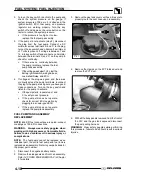
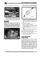
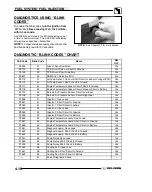
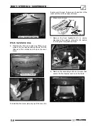
6. Relieve the fuel pressure at the fuel test valve.
Test Valve
7. Loosen the fuel tank hose and pull the fuel line
from the tank.
NOTE:
A small amount of fuel may
come out of the fuel line or tank. Plug the fuel line
and tank inlet or use a shop towel during removal.
CAUTION:
Check the fuel test valve for any possible fuel
seepage
after
performing
any
tests
or
procedures. Fuel is extremely flammable and
may cause severe burns, injury, or death. Do not
use any device that produces a flame or electrical
devices that may spark around fuel or fuel vapors.
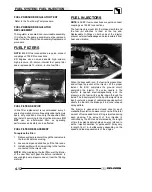
700 EFI Shown
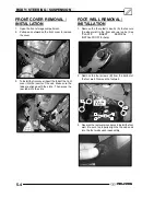
8. Remove the air box cover and remove the two gas
tank mounting bolts at the rear of the gas tank.
Front of ATV
Remove
2 Bolts
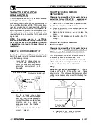
9. Carefully pull the fuel tank out of the frame. Keep
the fuel tank horizontal during removal, this will
keep the fuel in the tank from spilling out the top
inlet.
Fuel Pump/Tank Installation
1. Reinstall the pump/tank assembly.
2. Reconnect the sender wiring harness and route
the harness properly. Install the fuel line and
tighten the fuel line clamp.
3. Reinstall the two fuel tank mounting bolts at back
of tank.
4. Reinstall the PVT intake duct, gas tank vent line,
front cab assembly, and side panels.
NOTE:
Properly route the gas tank vent line, use tape
to secure the vent line in place. (See Pic 1).
5. Reconnect the negative battery cable. Test the
sender for proper operation.
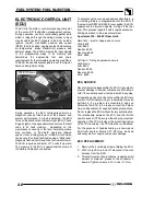
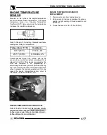
FUEL PRESSURE
REGULATOR
The fuel pressure regulator maintains the required
operating system pressure of 39 psi
±
3psi. A
rubber--fiber diaphragm divides the regulator into two
separate sections--, the fuel chamber and the pressure
regulating chamber. The pressure regulating spring
presses against the valve holder (part of the
diaphragm), pressing the valve against the valve seat.
The combination of atmospheric pressure and
regulating spring tension equals the desired operating
pressure. Any time the fuel pressure against the bottom
of the diaphragm exceeds the desired (top) pressure,
the valve opens, relieving the excess pressure,
returning the excess fuel back to the tank
.
Summary of Contents for Sportsman 800 Efi 2005
Page 116: ...ENGINE 3 62 NOTES ...
Page 136: ...FUEL SYSTEM FUEL INJECTION 4 20 NOTES ...
Page 186: ...CLUTCH 6 30 NOTES ...
Page 256: ...BRAKES 9 24 NOTES ...
Page 292: ...ELECTRICAL 10 36 BASIC WINCH WIRING 2005 ATV MODELS 2005 ATV WINCH WIRING DIAGRAM ...
Page 300: ...ELECTRICAL 10 44 NOTES ...
Page 301: ...ELECTRICAL 10 39 WIRING DIAGRAM 2005 SPORTSMAN 700 800 EFI Stator ...
Page 302: ...ELECTRICAL 10 40 WIRING DIAGRAM 2005 SPORTSMAN 700 800 EFI ...