4.34
ELECTRONIC FUEL INJECTION
FUEL PRESSURE REGULATOR
General Information
The fuel pressure regulator maintains the required operating
system pressure of 39 psi + 3psi. A rubber-fiber diaphragm
divides the regulator into two separate sections, the fuel
chamber and the pressure regulating chamber. The pressure
regulating spring presses against the valve holder (part of the
diaphragm), pressing the valve against the valve seat. The
combination of atmospheric pressure and regulating spring
tension equals the desired operating pressure. Any time the fuel
pressure against the bottom of the diaphragm exceeds the
desired (top) pressure, the valve opens, relieving the excess
pressure, returning the excess fuel back to the tank.
Fuel Pressure Regulator Test
Refer to the “FUEL PUMP TEST” procedure.
Fuel Pressure Regulator Replacement
The regulator is a sealed, non-serviceable assembly. If it is
faulty, the pump/tank assembly must be replaced. Refer to the
Fuel Pump / Tank Assembly Replacement procedure.
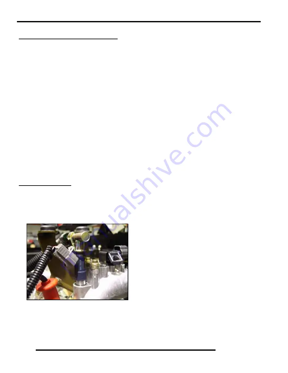
FUEL INJECTOR
General Information
The fuel injector mounts into the intake manifold, and the fuel
rail attaches at the top end. Replaceable O-Rings on both ends
of the injector prevent external fuel leakage and also insulate it
from heat and vibration.
When the key switch is on, the fuel rail is pressurized, and
voltage is present at the injector. At the proper instant, the ECM
completes the ground circuit, energizing the injector. The valve
needle in the injector is opened electromagnetically, and the
pressure in the fuel rail forces fuel down through the inside.
The “director plate” at the tip of the injector contains a series of
calibrated openings which directs the fuel into the intake port in
a cone-shaped spray pattern.
The injector is opened and closed once every other crankshaft
revolution. The total amount of fuel needed for one firing is
injected during each opening. The amount of fuel injected is
controlled by the ECM and determined by the length of time the
valve needle is held open, also referred to as the “injection
duration” or “pulse width”. It may vary in length from 1.5-8
milliseconds depending on the speed and load requirements of
the engine.
Fuel Injector Service
Injector problems typically fall into three general categories-
electrical, dirty/clogged, or leakage. An electrical problem
usually causes the injector to stop functioning.
NOTE: Do not apply voltage directly to the fuel
injector(s). Excessive voltage will burn out the
injector(s). Do not ground the injector with the
ignition “on”. lnjector will open/turn on if relay is
energized.
If an injector is not operating, it can indicate either a bad
injector, or a wiring/electrical connection problem. Check as
follows:
Injector leakage is very unlikely, but in rare instances it can be
internal (past the tip of the valve needle), or external (weeping
around the injector body). The loss of system pressure from the
leakage can cause hot restart problems and longer cranking
times.
Injector problems due to dirt or clogging are unlikely due to the
design of the injectors, the high fuel pressure, the use of filters
and the detergent additives in the gasoline. However, symptoms
that could be caused by dirty/clogged injectors include rough
idle, hesitation/stumble during acceleration, or triggering of
fault codes related to fuel delivery. Injector clogging is usually
caused by a buildup of deposits on the director plate, restricting
the flow of fuel, resulting in a poor spray pattern. Some
contributing factors to injector clogging include; dirty air
filters, higher than normal operating temperatures, short
operating intervals and dirty, incorrect, or poor quality fuel.
Cleaning of clogged injectors is not recommended; they should
be replaced. Additives and higher grades of fuel can be used as
a preventative measure if clogging has been a problem.
Injector
Injector
Summary of Contents for Ranger 500 2x4 2007
Page 1: ......
Page 20: ...1 18 GENERAL INFORMATION SAE Tap Drill Sizes Metric Tap Drill Sizes Decimal Equivalents ...
Page 82: ...3 23 ENGINE 3 Cylinder Head Exploded View EH50PL EFI Shown A A ...
Page 153: ...4 45 ELECTRONIC FUEL INJECTION 4 Fuel Pump Circuit Ignition Coil Circuit ...
Page 157: ...4 49 ELECTRONIC FUEL INJECTION 4 Diagnostic Connector Circuit ...
Page 296: ...10 10 ELECTRICAL POWER DISTRIBUTION MODULE NON EFI MODELS PDM Operation ...
Page 309: ...10 23 ELECTRICAL 10 EFI Cooling System Break Out Diagram PDM RD WH Key On 12 V Power ...
Page 332: ...10 46 ELECTRICAL Transmission Switch Circuit Differential Solenoid Circuit ...
Page 333: ...10 47 ELECTRICAL 10 Charging System Circuit Cooling Fan Circuit ...
Page 334: ...10 48 ELECTRICAL AWD Circuit ...
Page 339: ...WD 1 WIRE DIAGRAM RANGER 500 2X4 4X4 CHASSIS ...
Page 340: ...WD 2 WIRE DIAGRAM RANGER 500 2X4 4X4 DASH ...
Page 341: ...WD 3 WIRE DIAGRAM RANGER 500 EFI 4X4 CHASSIS PAGE 1 OF 2 ...
Page 342: ...WD 4 WIRE DIAGRAM RANGER 500 EFI 4X4 CHASSIS PAGE 2 OF 2 ...
Page 343: ...WD 5 WIRE DIAGRAM RANGER 500 EFI 4X4 DASH ...
Page 344: ...WD 6 WIRE DIAGRAM RANGER 500 EFI 4X4 BREAKOUTS ...
Page 345: ...WD 7 WIRE DIAGRAM RANGER 500 2X4 4X4 BREAKOUTS ...


