4.31
ELECTRONIC FUEL INJECTION
4
FUEL PUMP ASSEMBLY
Operation / Testing
NOTE: All EFI units utilize quick connect fuel lines.
An electric fuel pump assembly is used to transfer fuel to the EFI
system from inside the fuel tank. This assembly includes the fuel
pump, regulator and fuel gauge sender. The pump is rated for a
minimum output of 25 liters per hour at 39 psi and has a non-
serviceable internal 30-micron filter.
When the key switch is turned to "ON", the ECM activates the
fuel pump, which pressurizes the system for start-up.
The ECM switches off the pump preventing the continued
delivery of fuel in these instances:
• If the key switch is not promptly turned to the "start"
position.
• If the engine fails to start, or
• If the engine is stopped with the key switch "on" (as in
the case of an accident)
In these situations, the “check engine” light will go on, but will
turn off after 4 cranking revolutions if system function is OK.
Once the engine is running, the fuel pump remains on.
Fuel Pump Test
NOTE: The fuel pump/tank assembly is a non-
serviceable assembly and must be replaced if
determined to be faulty. If a fuel delivery problem is
suspected, make certain the filters are not plugged,
that the pump is being activated through the ECM,
all electrical connections are properly secured, the
fuses are good, and a minimum of 7.0 volts is being
supplied. If during starting, the battery voltage drops
below 7.0 volts, a reduction of fuel pressure may
occur resulting in a lean starting condition. If
required, testing of the fuel pump and circuitry may
be conducted.
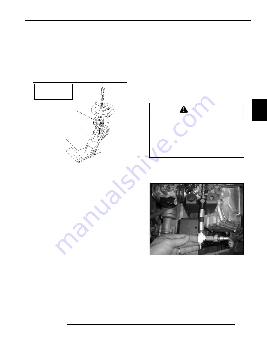
1. Insert the fuel test valve adapter
PU-47476.
Connect the
pressure hose of the Polaris pressure tester (
PN PU-43506-
A
) to the test valve. Route the clear hose into a portable
gasoline container.
Fuel pump not
replaceable, picture
for reference only.
Fuel Pump
Internal 30 Micron
Strainer (Bottom)
Regulator
CAUTION
Check the fuel test valve for any possible fuel
seepage after performing any tests or
procedures. Fuel is extremely flammable and
may cause severe burns, injury, or death.
Do not use any device that produces a flame or
electrical devices that may spark around
fuel or fuel vapors.
Summary of Contents for Ranger 500 2x4 2007
Page 1: ......
Page 20: ...1 18 GENERAL INFORMATION SAE Tap Drill Sizes Metric Tap Drill Sizes Decimal Equivalents ...
Page 82: ...3 23 ENGINE 3 Cylinder Head Exploded View EH50PL EFI Shown A A ...
Page 153: ...4 45 ELECTRONIC FUEL INJECTION 4 Fuel Pump Circuit Ignition Coil Circuit ...
Page 157: ...4 49 ELECTRONIC FUEL INJECTION 4 Diagnostic Connector Circuit ...
Page 296: ...10 10 ELECTRICAL POWER DISTRIBUTION MODULE NON EFI MODELS PDM Operation ...
Page 309: ...10 23 ELECTRICAL 10 EFI Cooling System Break Out Diagram PDM RD WH Key On 12 V Power ...
Page 332: ...10 46 ELECTRICAL Transmission Switch Circuit Differential Solenoid Circuit ...
Page 333: ...10 47 ELECTRICAL 10 Charging System Circuit Cooling Fan Circuit ...
Page 334: ...10 48 ELECTRICAL AWD Circuit ...
Page 339: ...WD 1 WIRE DIAGRAM RANGER 500 2X4 4X4 CHASSIS ...
Page 340: ...WD 2 WIRE DIAGRAM RANGER 500 2X4 4X4 DASH ...
Page 341: ...WD 3 WIRE DIAGRAM RANGER 500 EFI 4X4 CHASSIS PAGE 1 OF 2 ...
Page 342: ...WD 4 WIRE DIAGRAM RANGER 500 EFI 4X4 CHASSIS PAGE 2 OF 2 ...
Page 343: ...WD 5 WIRE DIAGRAM RANGER 500 EFI 4X4 DASH ...
Page 344: ...WD 6 WIRE DIAGRAM RANGER 500 EFI 4X4 BREAKOUTS ...
Page 345: ...WD 7 WIRE DIAGRAM RANGER 500 2X4 4X4 BREAKOUTS ...


