7.12
ELECTRICAL
Coolant Fan Control Switch Operation Test
1.
Place switch in a liquid bath and submerse it to the base of
the threads. Do not allow threads to contact container or an
inaccurate reading will result.
2.
Heat the liquid slowly and monitor the temperature with a
thermometer or Fluke™ meter pyrometer. The switch
should be closed (conductive) at the “ON” temperature
indicated in the chart, and stay conductive until the “OFF”
temperature is reached.
Fan Motor Current Draw
A current draw test will provide a good indication of fan motor
condition. A worn or damaged fan motor will draw more
current, which causes a reduction in blade speed and reduced
cooling.
1.
Turn key off. Disconnect harness from fan switch on
radiator.
2.
Place a jumper wire between the Red / Blk and Org / Blk
wires in the fan switch connector.
3.
Disconnect the fan and place a jumper wire between the
brown wires in the connectors. This will provide a ground
path to the fan. Use caution as to not damage the wire
terminals.
4.
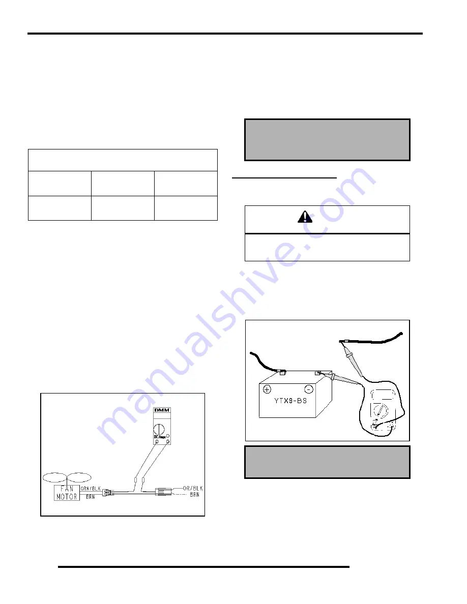
Place a DC ammeter in series as shown in the Illustration.
Verify fan blade is free to rotate.
5.
Turn ignition key and engine stop switch to “RUN”
position. Read the current draw on ammeter with fan
running.
6.
During start-up, the amperage should peak then decline
rapidly. If the motor continues to draw more amperage than
the fan circuit breaker rating during start-up, replace the
motor.
7.
If the fan motor draws more than 6.5 Amps during continual
running, check for debris blocking the fan, or replace the
motor.
CHARGING SYSTEM
Current Draw – Key Off
Connect an ammeter in series with the negative battery cable.
Check for current draw with the key off. If the draw is excessive,
loads should be disconnected from the system one by one until
the draw is eliminated. Check component wiring as well as the
component for partial shorts to ground to eliminate the draw.
Refer To Parts Manual For Fan Switch Application
Fan Switch Type
Continuity
(On)
No Continuity
(Off)
Off / On
Thermistor
180
o
F (82
o
C) ±
3
o
F
150
o
F (65
o
C)
± 8
o
F
Connect ammeter leads to
each service tool terminal
Connect BRN Wires
Fan Motor Current Draw:
Less Than 6.5 Amps
CAUTION
Do not connect or disconnect the battery cable
or ammeter with the engine running.
Damage will occur to electrical components.
Current Draw - Key Off:
Maximum of .01 DCA (10mA)
Current Draw Inspection
Key Off
RepairPro Service Manual
Summary of Contents for Outlaw 500
Page 1: ...Fix it like a Pro...
Page 3: ......
Page 47: ...NOTES MAINTENANCE 2 32 RepairPro Service Manual...
Page 81: ...3 34 ENGINE Outlaw Cam Timing Exploded View RepairPro Service Manual...
Page 149: ...NOTES BODY STEERING SUSPENSION 5 40 RepairPro Service Manual...
Page 195: ...NOTES ELECTRICAL 7 22 RepairPro Service Manual...
Page 200: ...8 1 WIRE DIAGRAM OUTLAW 500...
Page 201: ...8 2 WIRE DIAGRAM OUTLAW 500 RepairPro Service Manual...
Page 202: ...8 3 WIRE DIAGRAM OUTLAW 500...


