3.9
MAINTENANCE
3
Measure connecting rod big end side clearance with a feeler
gauge. 500/600/700 Liberty™ engines should have a clearance
of .011 - .030
"
(.28 -.75mm) and be equal on all rods within .002
"
(.05mm).
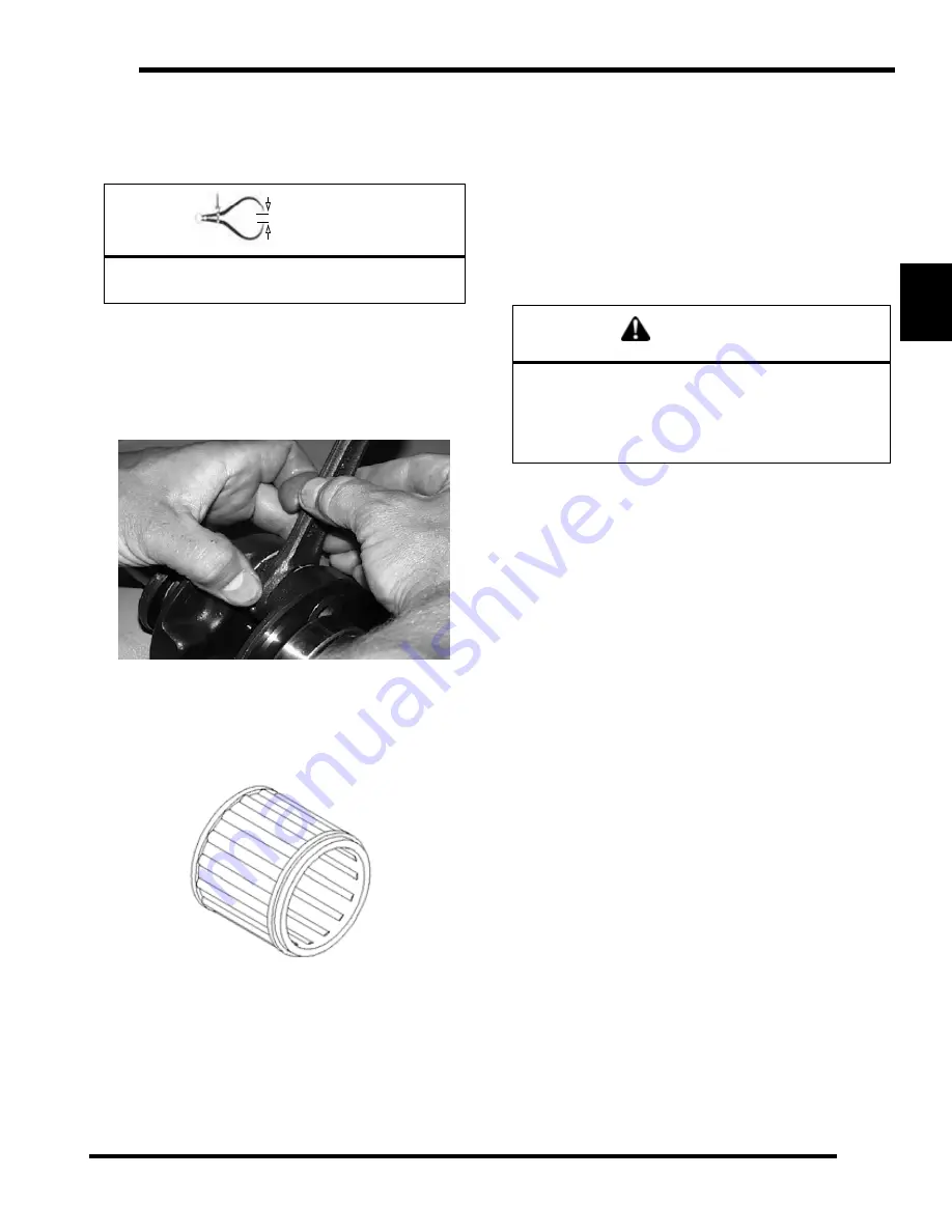
Rotate the connecting rod on the crankshaft and feel for any
rough spots. Check radial end play in rod by supporting rod
against one thrust washer and alternately applying up and down
pressure. Replace bearing, pin, and thrust washers if side
clearance is excessive or if there is any up and down movement
detectable in the big end bearing.
Wrist Pin Bearing
1.
Clean the end of the connecting rod and inspect inner bore
with a magnifying glass. Look for any surface
irregularities including pitting, wear, or dents.
2.
Run you fingernail around the inside of the rod and check
for rough spots, galling, or wear.
3.
Oil and install needle bearing and pin in connecting rod.
4.
Rotate pin slowly and check for rough spots or any
resistance to movement.
5.
Slide pin back and forth through bearing while rotating and
check for rough spots.
6.
With pin and bearing centered in rod, twist ends back and
forth in all directions to check for excessive axial play.
7.
Pull up and down evenly on both ends of pin to check for
radial play.
8.
Replace pin and bearing if there is any resistance to rotation
or excessive axial or radial movement. If play or roughness
is evident with a new pin and bearing, replace the
connecting rod.
Crankshaft Indexing
Polaris uses crankshafts that are pressed together. The
connecting rod journal center lines are indexed 180° apart from
each other.
It is sometimes necessary to check multi-cylinder crankshafts to
verify that one cylinder has not been forced out of position
relative to the other cylinder. Some causes for a “out of index”
crankshaft include but are not limited to the following:
• Hydrolock from water or fuel
• Impact to drive clutch from object or accident
• Abrupt piston or other mechanical failure
• Engine lock-up due to drive belt failure
Checking Crankshaft Index
1.
Remove the drive belt. See “Drive Belt Removal” on
page 6.10.
2.
Remove the drive clutch. See “Drive Clutch Removal” on
page 6.15.
3.
Securely fasten a large degree wheel on the flywheel or
PTO end of the crankshaft. Make sure that it is mounted
concentrically with the crankshaft center line.
4.
With a section of wire (wire coat hanger), anchor it to a
convenient spot. Bend one end at the outer perimeter of the
degree wheel as shown below.
5.
Install a dial indicator into the magneto end cylinder spark
plug hole. The ignition timing is referenced by the magneto
end.
6.
Locate TDC as accurately as possible by finding the center
of the point where there is no piston movement note the
“Zero” the dial indicator at this point.
=
In. / mm.
500/600/700 Liberty Engine Connecting Rod (Big
End) Side Clearance: .011-.030" (.28-.75mm)
NEEDLE BEARING
CAUTION
Disconnect the battery ground cable and ALL spark
plug high tension leads. Ground high tension leads to
the engine. Disconnect lanyard (if equipped) and/or
press the engine stop switch before proceeding with
the following procedure.
Summary of Contents for 340 LX 2007
Page 4: ......
Page 40: ...NOTES MODEL SPECIFICATIONS 1 36...
Page 51: ...2 11 GENERAL 2 SPECIAL TOOLS Special Tools...
Page 52: ...2 12 GENERAL...
Page 53: ...2 13 GENERAL 2...
Page 54: ...2 14 GENERAL...
Page 80: ...NOTES MAINTENANCE 3 26...
Page 91: ...4 11 FUEL DELIVERY 4 Throttle Opening Vs Fuel Flow VM only...
Page 104: ...NOTES FUEL DELIVERY 4 24...
Page 114: ...5 10 ENGINE 500 600 Touring WideTrak LX Touring WideTrak...
Page 146: ...NOTES ENGINE 5 42...
Page 170: ...NOTES CLUTCHING 6 24...
Page 214: ...NOTES FRONT SUSPENSION STEERING 8 20...
Page 259: ...10 11 CHASSIS HOOD 10...
Page 260: ...NOTES CHASSIS HOOD 10 12...
Page 272: ...11 12 BATTERY ELECTRICAL SYSTEMS ELECTRIC START GEN II EDGE System Schematic...
Page 277: ...11 17 BATTERY ELECTRICAL SYSTEMS 11 System Schematic 600 700 CFI...
Page 286: ...11 26 BATTERY ELECTRICAL SYSTEMS Chassis Relay...
Page 288: ...11 28 BATTERY ELECTRICAL SYSTEMS Vehicle Speed Sensor...
Page 293: ...11 33 BATTERY ELECTRICAL SYSTEMS 11 CFI Power System CFI Ignition Injection Power...
Page 294: ...11 34 BATTERY ELECTRICAL SYSTEMS CFI Crank Position System CFI Safety Stop System...
Page 295: ...11 35 BATTERY ELECTRICAL SYSTEMS 11 CFI Full Load Fuel Injectors CFI Part Load Fuel Injectors...
Page 296: ...11 36 BATTERY ELECTRICAL SYSTEMS CFI Chassis Power CFI Ignition Coils...
Page 297: ...11 37 BATTERY ELECTRICAL SYSTEMS 11 CFI TBAP Sensor CFI TPS Engine Temp Sensors...
Page 298: ...11 38 BATTERY ELECTRICAL SYSTEMS CFI Exhaust Solenoid CFI Knock Sensor...
Page 299: ...11 39 BATTERY ELECTRICAL SYSTEMS 11 CFI Fuel Pump CFI Diagnostic Connections...
Page 300: ...11 40 BATTERY ELECTRICAL SYSTEMS CFI MFD Circuits CFI MFD Power Circuits...
Page 301: ...11 41 BATTERY ELECTRICAL SYSTEMS 11 CFI Fuel Level Circuit CFI Vehicle Speed Circuit...
Page 302: ...11 42 BATTERY ELECTRICAL SYSTEMS CFI Mode Set Switch CFI PERC Switch...
Page 318: ...12 1 Wiring Diagrams 2007 340 550 GEN II EDGE Models...
Page 319: ...12 2 Wiring Diagrams 2007 Wide Trak...
Page 320: ...12 3 Wiring Diagrams 2007 500 XCSP...
Page 321: ...12 4 Wiring Diagrams 2007 600 HO Carbureted 1 of 2...
Page 322: ...12 5 Wiring Diagrams 2007 600 HO Carbureted 2 of 2...
Page 323: ...12 6 Wiring Diagrams 2007 600 HO Carbureted Hood Harness...
Page 324: ...12 7 Wiring Diagrams 2007 600 700 CFI 1 of 2...
Page 325: ...12 8 Wiring Diagrams 2007 600 700 CFI 2 of 2...
Page 327: ...12 10 Wiring Diagrams...


