14
Pub. No. OM-A-10E — April 2004
9.
Slowly open the dryer outlet isolation valve to
pressurize the downstream system.
10. Use the manual advance button to cycle the dryer
through the valve sequences.
Adjustments & Settings
1.
At start-up note the blower pressure. The intake filter
should be changed when there is a significant drop
in blower pressure.
2.
Adjust the cooling flow pressure at the recommended
level ______ PSIG.
3.
Set heater thermostat TH1. 390°F (Located in the
bottom of the heater shell)
4.
Set over temperature thermostat TH2. 200°F.
(Located in the top of the heater shell)
5.
Set desiccant bed thermostat TH3/TH4. 250°F.
6.
Set heater failure thermostat TH5. 300°F. (Located in
the bottom of the heater shell) Optional
7.
Set heater failure time delay relay 3 HRS. Optional
8.
Set failure to shift time delay relay 5 HRS. Optional
9.
Check and set the dewpoint monitor Setpoint
Settings. Settings are factory preset. See dewpoint
display setting on Page 19.
10. Open the bleed valve on the optional dewpoint
sensor probe.
11. Dewpoint Demand Setpoint (SP1): ______
12. High Humidity Alarm Setpoint (SP2): ______
Sequence of Operation
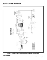
The sequence of operation of the External Heat
Reactivated Blower Purge Dryer can be readily followed
by referring to the following flow schematic and timing
sequence.
During initial start-up with the power switch in the OFF
position, and the towers pressurized with air, both inlet
valves stay in the OPEN position and the purge valves stay
in the CLOSED position. This type of fail safe valve
operation allows the air to dry through both the towers,
without any purge in the event of loss of power to dryer.
This will give you extended drying time until desiccant
chambers are saturated.
The desiccant is designed to handle air saturated with
water vapor only. Any liquids or slugs of water tend to
decrease the efficiency of the desiccant and retard the
regeneration process to provide the designed dewpoint.
With the power switch in the ON position at
time equal to 0.0 hrs.,
the left tower air inlet valve is
open to allow the air to pass through the left tower. The
right tower inlet valve is closed. The saturated compressed
air/gas passes through the desiccant in the left tower
where the desiccant adsorbs the moisture, and the dry air
at a pressure dewpoint of -40°F or less exits through the
left outlet check valve and goes out into the plant air
system through the afterfilter.
At time equal to 5 minutes,
the right tower purge
valve depressurizes the right tower so that the desiccant is
not disturbed.
At time equal to 10 minutes,
the blower and heater
are energized to commence the regeneration cycle.
The temperature of the purge air is controlled by the
heater control thermostats to maintain the preset
temperature. During the heating cycle, the bed
temperature should rise to 250°F (121°C) in
approximately two hours. The heater control thermostats
will cycle the heater to maintain this 250°F bed
temperature. The hot purge air passes through the right
purge flow check valve and enters the desiccant bed at the
top of the tower. The hot purge air removes the previously
adsorbed water vapor from the desiccant and purges out
through the right purge valve, and is exhausted into the
atmosphere through the exhaust muffler.
NOTE:
During the regeneration air flow through the
desiccant bed, the tower pressure gauge should read 0
PSIG. Any higher pressure is an indication of a plugged
muffler, which will retard the regeneration of desiccant. In
the event of a leaking valve or check valve a back
pressure will develop. A significant back pressure will
cause the blower amps to increase and kick off the blower
on high overloads.
At time equal to 3 hrs.,
the blower and heater are de-
energized, and the cooling flow valve opens to start the
cooling cycle to reduce the temperature in the desiccant
bed and prepare it for the drying cycle.
NOTE:
As soon as the cooling cycle begins, adjust the
purge adjustment valve to the recommended purge control
setting. This adjustment should only be required once, and
then the locking mechanism should be locked in place.

