background image

Connecting Multiple Control Units

By default, the first Control Unit added to the CCF is automatically assigned the Master sync priority. Every CCF must
contain one master Control Unit, which is set through CrewWare. Secondary and Tertiary sync priority assignments
are not currently operational.

Caution:

Loading or having a previously loaded CCF on any CU other than the Master CU will cause a

configuration malfunction. See

"Delete Configuration File (CCF)" on page 35

for more information on

and resolving this issue.

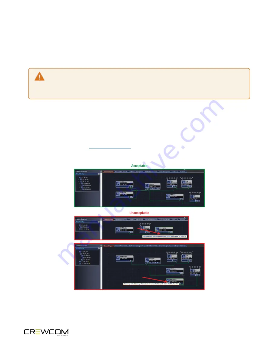
CrewNet supports up to 4 Control Units. These additional Control Units can be connected to the network via an
available CrewNet port on another Control Unit or a CrewCom Hub. No Control Unit additions can be made via an RT's
CrewNet port. Multiple Control Units may only be connected together (i.e., daisy-chained) when they are connected
directly from the Master Control Unit. A single Control Unit may be connected from a CrewCom Hub; this configuration
is not considered to be daisy-chaining the CUs. See the images below for examples of acceptable and unacceptable
multi-CU system diagrams. See

the CrewWare Manual

for more information on building system diagrams in

CrewWare.

Figure 18

Control Unit Configuration Limitations

Setup and Installation - 37

Summary of Contents for Crewcom CCU-22

Page 1: ...Control Unit OPERATING MANUAL...

Page 2: ...ii...

Page 3: ...technologies com Phone 1 334 321 1160 Toll Free 1 844 475 4268 or 1 844 4PLIANT Fax 1 334 321 1162 Copyright 2018 2020 Pliant Technologies LLC All rights reserved The Pliant CrewCom and CrewNet word m...

Page 4: ...tion 5 What s in the Box 6 Firmware Release Notes 7 CrewCom Overview 8 Decentralized Network Architecture 8 Flexible RF Platform 8 Intuitive User Experience 8 CrewCom Devices 9 CrewWare 10 CrewCom Con...

Page 5: ...stall Control Units 29 Connect to CrewNet 30 Power On the System 31 How to Power On and Configure the System 31 Upload Configuration File CCF 32 Loading a CrewCom Configuration File via USB 32 Uploadi...

Page 6: ...sting LCD Display Settings 47 Link Quality 50 Save Configuration File CCF 51 Wired Settings 52 Intercom Settings Menu 52 2 Wire Intercom Connectivity 56 4 Wire Intercom Connectivity 58 Auxiliary In 60...

Page 7: ...l Unit 72 LAN Configuration via CrewWare 74 Call 75 Set Up Call 75 Adjusting Access Rights 76 Levels of Access 76 Software Access Rights 76 System Access Rights 76 Setting Passcode 77 Restore Factory...

Page 8: ...License and Compliance Information 86 License Information 87 Warranty Information 88 Warranty Information 89 Limited Warranty 89 Parts Limited Warranty 90 Table of Contents viii...

Page 9: ...ORMATION This chapter consists of the following sections Control Unit Safety Information 2 Safe Operation Recommendations 2 Safe Installation Recommendations 3 Power Information 3 CHAPTER 1 Safety Inf...

Page 10: ...rs on or near the unit l Do not place unit in areas where it will be exposed to weather l Plug the Control Unit directly into an AC power inlet Avoid using extension cords to power unit l Ensure the p...

Page 11: ...he equipment in an environment compatible with the maximum ambient temperature Tma specified in Control Unit Specifications on page 80 l Reduced Air Flow Installation of the equipment in a rack should...

Page 12: ...te end o An IEC C13 plug has three pins The center pin carries the earth ground The remaining two pins carry neutral and live circuits o The conductors of the mains cords shall have adequate cross sec...

Page 13: ...ork Architecture 8 Flexible RF Platform 8 Intuitive User Experience 8 CrewCom Devices 9 CrewWare 10 CrewCom Configuration File CCF 11 CrewCom Configuration File Defaults 11 Determining Which CCF is Ac...

Page 14: ...Follow the product registration instructions on the Warranty Extension Registration Card and visit Pliant s Product Registration Page to extend your product warranty to two years at no charge See War...

Page 15: ...Firmware Release Notes Find the latest CrewCom firmware release notes on the Pliant Technologies website Download the latest firmware release from the Pliant Technologies downloads page Introduction 7...

Page 16: ...reless communication challenge facing production and entertainment professionals worldwide Each CrewCom wireless product is available in the 2 4GHz and 900MHz North America Australia and New Zealand o...

Page 17: ...ogging The RP requires a connected headset and access to a Radio Transceiver on the CrewCom system Devices are available in 2 4GHz and 900MHz bands as well as two and four volume talk button configura...

Page 18: ...onfiguration File offline and then load the settings to your system from a portable USB drive or from a connected computer CrewWare provides an intuitive method of accessing all connected CrewCom devi...

Page 19: ...ther to create channels of communication between CrewCom users They are defined for each user stored in the CCF and available each time you set up For more information on building a system diagram and...

Page 20: ...onference subscribers accordingly This method of subscription based audio using Conferences is very powerful Point to point associations may also be easily constructed using this method Each associati...

Page 21: ...lity of an RP s local controls knobs and buttons including Conference assignments and allows customization for user preferences and roaming l Global Profile Settings These settings are part of the Cre...

Page 22: ...on the system from the Control Unit LCD by accessing the Control Unit s System Configuration menu Because a system supports up to 64 Profiles you can sort Profiles alphanumerically by Name or by Type...

Page 23: ...s must be used PPS 48V 02 included with Hub sold separately with all other devices l Fiber Optical Ports For a fiber CrewNet port a Single Mode Fiber cable duplex LC connector will be required up to 3...

Page 24: ...r must be supplied to that device using a Pliant 48VDC power supply PPS 48V 02 included with Hubs sold separately for all other devices Once local power is supplied to the device downstream devices ma...

Page 25: ...ter consists of the following sections Control Unit 18 CCU 44 Front 18 CCU 44 Rear 20 CCU 22 22 Control Unit Display 24 Home Operating Screen 24 Secondary Operating Screen 25 Control Unit Menu 26 CHAP...

Page 26: ...male Use the Local button letter I in the figure above to adjust local headset settings from the CU A compatible headset must be provided by the user See Local Headset on page 70 for connection pinou...

Page 27: ...n makes adjustments in edit mode l Left Moves the cursor or level setting to the left on screen l Right Moves the cursor or level setting to the right on screen l Enter Center Selects the current curs...

Page 28: ...external devices the Stage Announce SA Relay and four additional GPO relays The user has access to both the normally open and the normally closed contacts for each relay Rated load for all relay cont...

Page 29: ...tings can be adjusted under the Wired Settings menu or via CrewWare See 4 Wire Intercom Connectivity on page 58 F STAGE ANNOUNCE SA Stage Announce SA is used to output system audio to a dedicated audi...

Page 30: ...nced systems Each Sync In port s status LEDs indicate the status of the sync link See Control Unit LEDs on page 45 CCU 22 The CCU 22 model has the same controls and functions as the CCU 44 with two ex...

Page 31: ...er isolated These connections do not use standard CAT 5e cables The cables used must be wired per the CrewCom pin connections and per the device to which you are connecting See More About the CrewCom...

Page 32: ...k Quality Indicator LQ provides a diagnostic measurement of actual packet transmission from Radio Pack to Radio Transceiver and vice versa The LQ value on the Control Unit LCD represents the lowest LQ...

Page 33: ...acks Press the Home button once to toggle between the Primary and Secondary screens After 60 seconds the screen will time out and revert back to the Home screen Figure 9 ControlUnit Secondary Operatin...

Page 34: ...Control Unit Menu The following menu tree displays the Control Unit s primary menu options and settings Figure 10 ControlUnit Menu Product Overview 26...

Page 35: ...CCF 32 Loading a CrewCom Configuration File via USB 32 Uploading a CrewCom Configuration File via CrewWare 34 Delete Configuration File CCF 35 Add More CrewCom Devices 36 Connecting Multiple Control...

Page 36: ...ram contact the person who provided your CrewCom system for assistance or contact Pliant Customer Support If your CU has not been pre configured with a CCF and if you do not have a saved CCF on a USB...

Page 37: ...able How To Install Control Units 1 Place the CU on a flat dry surface or in a desired rack mounted location rack screws not included Wherever it is placed ensure that the air input and output section...

Page 38: ...up to 330 ft 100 m in length Any CrewCom device connected to CrewNet via a Cat 5e or greater cable will receive Power Over CrewNet PoC via the CrewNet port See Power Over CrewNet on page 15 for more...

Page 39: ...ting Multiple Control Units on page 37for more information about CU priority 4 Verify that your RTs and Hubs if applicable are receiving power by checking that their Power LEDs are green Under optimal...

Page 40: ...the procedure below to load a new CrewCom Configuration File CCF to your system Important Be sure you have saved a backup copy of your current configuration file prior loading a new one in case you n...

Page 41: ...it Figure 12 CULCD List of AvailableConfiguration Files Note Only CCFs that have been properly named with 8 characters or less will be available for selection from this list See Save Configuration Fi...

Page 42: ...ol Unit when it displays the following message CCF Changed Power down Master CU for 10 seconds for configuration changes to take effect Figure 15 CULCD Power Down Prompt 8 Remove your USB drive and po...

Page 43: ...SB Drive menu screen will display on the CU LCD 2 Use the CU s navigation buttons to scroll through the list of menu options on the CU s LCD until Delete System Configuration is highlighted Press the...

Page 44: ...re then save the Configuration File change and apply the new Configuration File to your system Remember you cannot make System Diagram changes while CrewWare is live See the CrewWare Manual for inform...

Page 45: ...up to 4 Control Units These additional Control Units can be connected to the network via an available CrewNet port on another Control Unit or a CrewCom Hub No Control Unit additions can be made via a...

Page 46: ...he CU to the device micro end goes into the RP s USB port beneath its rubber port cover The RP will power on by itself 2 Follow the prompts that display on the RP LCD A Your RP must match the system f...

Page 47: ...teps 1 6 until every RP is paired Note RP Pairing does not require a CU connection to CrewWare but if you are using CrewWare RPs can be paired while the program is offline or online When online you sh...

Page 48: ...the 2 wire intercom ports s on the back of the CU For full connection and configuration instructions see 2 Wire Intercom Connectivity on page 56 l If connecting a 4 wire intercom system connect it to...

Page 49: ...anual and or the How to Edit a Profile video tutorial Change CU Name from the CU 1 Scroll through the CU Settings options and select Control Unit Name to enter edit mode 2 Use the CU s up down navigat...

Page 50: ...it is critical that each system be configured within certain parameters Primarily hopping patterns and frequency bands should be manually coordinated between systems o Radio band settings are configu...

Page 51: ...y 50 Save Configuration File CCF 51 Wired Settings 52 Intercom Settings Menu 52 2 Wire Intercom Connectivity 56 4 Wire Intercom Connectivity 58 Auxiliary In 60 Auxiliary Out 62 Nulling 64 Relays 66 St...

Page 52: ...ne 70 Using the Local Headset 71 Local Headset Pinout and Wiring 71 Local Area Network LAN Settings 72 LAN Configuration via Control Unit 72 LAN Configuration via CrewWare 74 Call 75 Set Up Call 75 Ad...

Page 53: ...link is detected Blinking Green Activity is detected Off No CrewNet connection detected LAN LEDs Left Blinking Green LAN link is connected Green No LAN connection detected Right Off LAN activity is d...

Page 54: ...ol Unit CU will not function until unlocked except for the power switch which will power the unit off and the Volume knob and Talk button which will allow communication with a connected local headset...

Page 55: ...l for more information Naming a Control Unit See Name a Device on page 41 Adjusting LCD Display Settings The LCD display has a few adjustable settings such as Contrast Brightness and Backlight Time Ou...

Page 56: ...ControlUnit LCD Backlight Brightnes LCD Timeout Enables users to set the amount of time the LCD s backlight will stay lit after engaging the Control Unit s interface Select either 60 30 or 10 seconds...

Page 57: ...ust the brightness of the Control Unit LED indicators Talk LED for local headset on front of CU Select either High Medium Low or Off The default setting for LED brightness is High Figure 23 Edit Contr...

Page 58: ...issue related to interference or the Radio Pack l What should the LQ value be during operation The LQ will not remain at an exact value during system operation Depending on what degree of outside int...

Page 59: ...uired file name format for a CCF uploaded via USB drive is 8 characters or less with no spaces or special characters e g 12345678 ccf Also make sure the USB drive you are saving to has enough availabl...

Page 60: ...his CU menu option displays all the 2 Wire and 4 Wire settings on the CU LCD Due to LCD size constraints only four ports are viewable at a given time Use the Navigational Controls on the front of the...

Page 61: ...ot control 4 Wire operation When connecting to a 4 Wire intercom system you must enable the port On Off before using The default setting for Intercom Type is OFF Figure 26 2 WireIntercom TypeOptions 3...

Page 62: ...ic kill signals from entering or leaving CrewCom via the respective port Mic Kill signals can still be generated and transmitted by entities across CrewNet The default setting for Mic Kill is OFF Note...

Page 63: ...ve The default setting for 2 Wire Intercom In is 6 The default setting for 4 Wire Intercom In is 0 The OUT level control adjusts the outgoing level from CrewCom of the currently selected wired interco...

Page 64: ...tion about navigating this CU menu Under the Wired Settings menu select Intercom Settings 1 Use the Navigational controls to navigate to the desired setting for a 2 Wire port CCU 22 ports 1 and 2 CCU...

Page 65: ...g on page 64 for more information 4 Adjust IN OUT audio levels between the CrewCom System and the 2 Wire intercom system as needed A With appropriate mic gain settings and expected nominal levels from...

Page 66: ...sired setting for a 4 Wire port CCU 22 ports 3 and 4 CCU 44 ports 5 through 8 A For intercom type press Enter to turn the port on or off use the navigation buttons to scroll through the list and press...

Page 67: ...s vary and it is important to ensure that the cable is wired correctly for proper system operation CrewCom utilizes RJ 45 jacks for connection to a 4 Wire port Only two pairs of wires are utilized one...

Page 68: ...ems Audio supplied to Aux IN can be assigned to any combination of up to 10 possible Conferences The default setting for Aux IN Level is 0 Conference assignment changes and level adjustments can be pe...

Page 69: ...rough the menu options to the Wired Settings and select Aux In 1 Use the navigation controls to scroll to the Master Level bar Press Enter to select it Note Individual Aux In assignment level adjustme...

Page 70: ...rewCom audio entity such as Radio Packs and the local headset of a Control Unit CU The default setting for Aux OUT Level is 0 Conference assignment changes and level adjustments can be performed via C...

Page 71: ...enu options to the Wired Settings and select Aux Out 1 Use the navigation controls to scroll to the Master Level bar Press Enter to select it Note Individual Aux Out assignment level adjustments are n...

Page 72: ...channel being nulled are interrupted The nulling process takes approximately 10 15 seconds per channel You may need to re adjust the intercom levels to a proper level after the 2 Wire intercom lines h...

Page 73: ...s it connects to connected wired systems however those wireless Radio Packs will still communicate with one another while the null is in progress Figure 33 AutoNullin Process B After you confirm to pr...

Page 74: ...onnector on the rear of the Control Unit Figure 34 Relay Pin Diagram Relay Setup To connect and enable relays to external General Purpose Output GPO connect any or all of the relays via the DA 15 Rela...

Page 75: ...or on the CU Pressing the SA button enables the headset microphone regardless of the status of the Talk buttons If enabled all RPs can access this feature If more than one CU is present SA audio will...

Page 76: ...the Control Unit CU Then configure the connection either via CU or CrewWare Configure Stage Announce via CU Configure and set the SA audio level via the CU s Wired Settings menu Figure 36 StageAnnoun...

Page 77: ...re Changing Profile Assignments from the CU 1 Access the CU s Radio Pack Settings menu Do this quickly by pressing the Packs button on the front of the CU 2 Choose a method by which to sort the paired...

Page 78: ...clipping feedback or echo When set too low words may sound too quiet to other listeners Headsets by different manufacturers or different models of headsets will require widely varying Mic Gain settin...

Page 79: ...the microphone will remain enabled Pressing and holding TALK will cause the button to act in a momentary fashion The white TALK LED will remain lit and the microphone will remain enabled only as long...

Page 80: ...nit LAN Configuration via Control Unit The following settings and processes can be found in the Control Unit s menu under LAN Settings When changing LAN settings from the CU front panel a reboot is re...

Page 81: ...CrewWare In Manual mode input your desired TCP IP Address on this screen using the CU s navigation buttons Press the CU s enter button when done to save changes Figure 39 TCP IP Address Input Subnet M...

Page 82: ...n if needed for setting up your LAN connection Figure 42 MACAddress Read Only Screen Port Number The default Port value to connect to a Control Unit is 2017 This setting is not currently viewable from...

Page 83: ...e conference or a signal will be sent to any connected 2 wire devices associated with that conference as long as outbound call is enabled for the associated CU port Call can be enabled for both wirele...

Page 84: ...designation which does not alter the System Access setting i e does not alter access to the Control Unit and Radio Pack menus for those users CrewCom settings within CrewWare are view only when CrewW...

Page 85: ...Level and then choose either Admin or User Set System Access Level from CrewWare See the CrewWare Manual for more information about this process Setting Passcode Set Passcode from Master Control Unit...

Page 86: ...com Type OFF X Intercom Call OFF X Intercom Mic Kill OFF X Intercom EchoCan ON 2 Wire OFF 4 Wire X Intercom IN 2w 4w 2W 6 4W 0 X Intercom OUT 2w 4w 2W 4 4W 0 X Auxiliary IN 0 X Auxiliary OUT 0 X SA Re...

Page 87: ...PRODUCT SPECIFICATIONS This chapter consists of the following sections Control Unit Specifications 80 CHAPTER 6 Product Specifications 79...

Page 88: ...h XLR 3M loop 2 ports 4 ports via XLR 3F with XLR 3M loop 4 ports 2 Wire Compatibility Clear Com RTS and AudioCom Balanced 4 Wire Intercom Connection 2 ports via RJ 45 4 ports via RJ 45 Stage Announce...

Page 89: ...Yes Notice About Specifications While Pliant makes every attempt to maintain the accuracy of the information contained in this manual this information is subject to change without notice and publishe...

Page 90: ...PRODUCT SUPPORT This chapter consists of the following sections Product Support 83 Returning Equipment for Repair or Maintenance 83 CHAPTER 7 Product Support 82...

Page 91: ...uipment directly to the factory without first obtaining a Return Material Authorization RMA Number Obtaining a Return Material Authorization Number will ensure that your equipment is handled promptly...

Page 92: ...SYSTEM MAINTENANCE AND STORAGE This chapter consists of the following sections System Maintenance and Storage 85 Cleaning 85 Temperature and Humidity 85 CHAPTER 8 System Maintenance and Storage 84...

Page 93: ...environmental conditions however you should take all necessary precautions to keep your system devices safe dry and out of extreme conditions The Radio Transceiver is weather resistant including gaske...

Page 94: ...LICENSE AND COMPLIANCE INFORMATION This chapter consists of the following sections License Information 87 CHAPTER 9 License and Compliance Information 86...

Page 95: ...l interference to radio communications Operation of this equipment in a residential area is likely to cause harmful interference in which case the user will be required to correct the interference at...

Page 96: ...WARRANTY INFORMATION This chapter consists of the following sections Warranty Information 89 Limited Warranty 89 Parts Limited Warranty 90 CHAPTER 10 Warranty Information 88...

Page 97: ...y does not cover any defect malfunction or failure caused by circumstances beyond the control of Pliant Technologies LLC including but not limited to negligent operation abuse accident failure to foll...

Page 98: ...ized by Pliant Technologies LLC and shipping damage Any damage done to a replacement part during its installation voids the warranty of the replacement part This limited warranty is the sole and exclu...

Reviews: