Planmeca Ethernet interface 9
INSTALLATION OF THE PLANMECA ETHERNET INTERFACE BOX TO THE PLANMECA PROLINE XC X-RAY
Installation manual
3.2
Installing Planmeca Ethernet Interface
1.
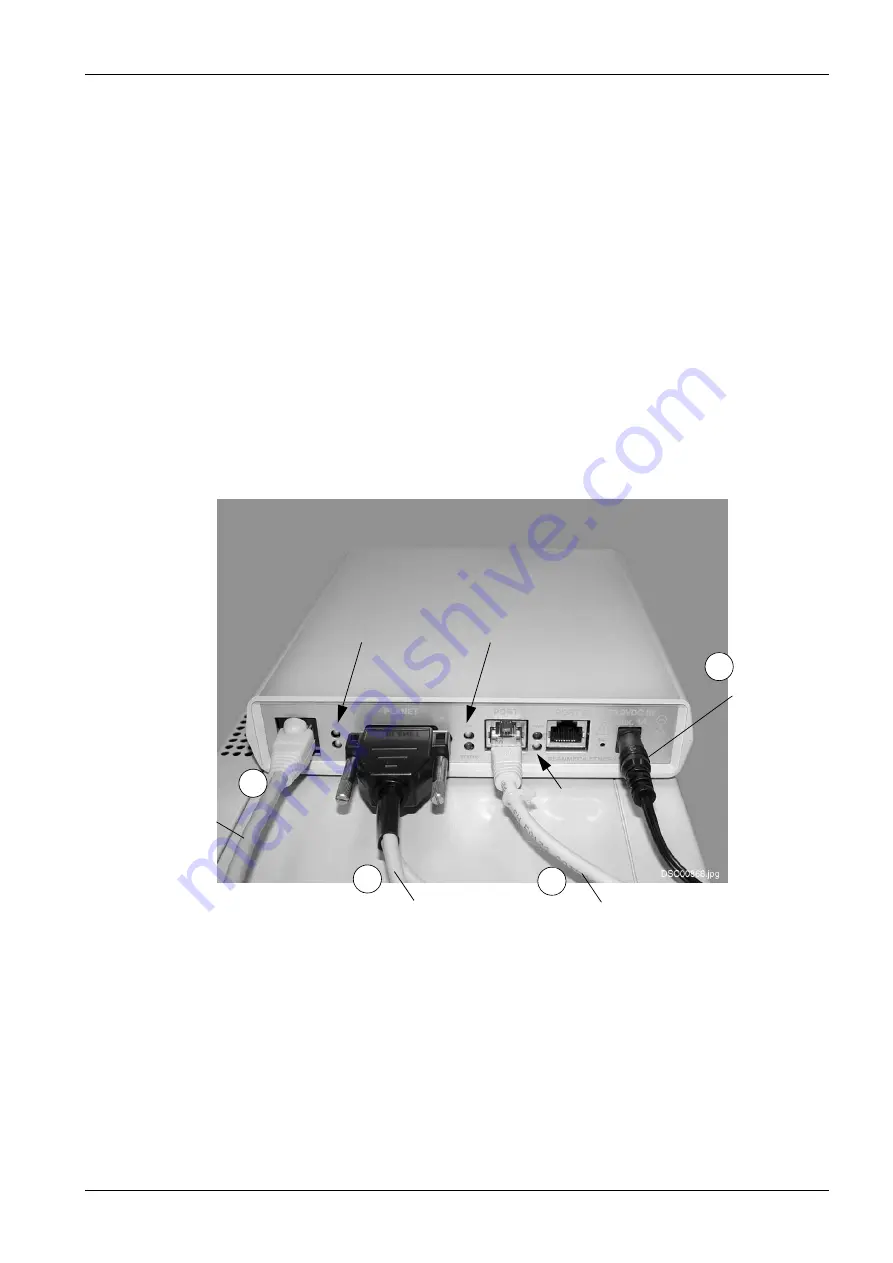
To install the Planmeca Ethernet Interface first attach the Ethernet interface box to the
power supply and plug the power supply to the mains. Check that the
OK
indicator light
on the Planmeca Ethernet Interface box comes on (see picture below).
2.
Attach the RJ45 Cat. 5 UTP cable from 10/100 Base-T directly to the hub or the cross-
connected Cat. 5 UTP cable to the computer. The
Link
light starts to flash on the
Planmeca Ethernet Interface.
3.
Connect the Planet grabber cable to the Planer connector and connect the
interconnection cable to the Planet grabber cable.
If you are NOT connecting any other equipment to the PC, use the Planet grabber cable
with one connector. In this case connect the PC data cable to Port
1
.
When using the Planet grabber cable with two connectors note, that the connectors of
the Planet grabber cable with two connectors are numbered. If you connect the
interconnection cable to connector number
1
, you must connect the PC data cable to the
port
1
, and if you connect the interconnection cable to connector number
2
, you must
connect the PC data cable to the port
2
.
4.
Connect the PC data cable from Planmeca Proline XC keyboard processor PCB either to
Port
1
or Port
2
(or to both of them in case you use two systems). Check also that the
PWR
(power)
light comes on.
Install the Dimaxis Pro or Dimaxis Classic software to your computer in case it is not yet
installed (refer to Dimaxis Installation manual, publication number 10006119).
Power supply
cable
OK indicator light
RJ45 or
Link
PWR
1
2
4
3
PC data cable
Planet grabber cable and
interconnection cable
Cross-connected
cable
Summary of Contents for Ethernet Interface
Page 26: ......


