10/100/1000Mbps
Intelligent Stackable Switch
SGSW-2402
User’s Manual
Page 1: ...10 100 1000Mbps Intelligent Stackable Switch SGSW 2402 User s Manual ...
Page 2: ...improvements to this User s Manual and or to the products described in this User s Manual at any time without notice If you find information in this manual that is incorrect misleading or incomplete we would appreciate your comments and suggestions FCC Warning This equipment has been tested and found to comply with the limits for a Class A digital device pursuant to Part 15 of the FCC Rules These ...
Page 3: ...3 10 SNMP 18 3 11 RMON STATISTICS 19 3 12 PORT SECURITY 20 3 12 1 Setting Up Procedures 21 3 12 2 Delete MAC Address 21 3 13 MIRROR PORT 21 3 13 1 Using Mirror Port to Monitor Traffic 21 3 13 2 Setup Procedures 22 3 14 AGING CONTROL 22 3 15 ADDRESS SEARCH 23 3 15 1 Host Searching Procedures 24 3 15 2 MAC Address Search 25 3 16 SYSTEM TOOLS 26 3 17 SYSTEM CONFIG 26 3 18 SYSTEM INFORMATION 27 3 19 C...
Page 4: ... enable port number h f 10 100 1000 A 51 4 2 18 port set disable port number 52 4 2 19 port set flw port number on off 52 4 2 20 port set bck port number on off 52 4 2 22 port set vid port number v vid 53 4 2 23 vlan VLAN Management Commands 54 4 2 24 vlan show 54 4 2 25 vlan build vid u untags t tags p priority 55 4 2 26 vlan delete vid 55 4 2 27 vlan set pri vid p priority 55 4 2 28 trunk TRUNK ...
Page 5: ...ase T Intelligent Switch Modules and Gigabit 1000Base SX LX Intelligent Fiber Modules With its build in Web based Management managing and configuring the SGSW 2402 Intelligent Switch becomes easier From cabinet management to port level control and monitoring you can visually configure and manage your network via Web Browser just click your mouse instead of typing cryptic command strings However th...
Page 6: ...t 2 for 1000Base SX LX T and 100Base FX modules Stack Interface Through Ethernet interface Up to 8 units can be managed by single IP Switch Fabric 9 6Gbps Switch Processing Scheme Store and forward Throughput packet per second 6 547Mpps Address Table 4K entries Queue Buffer 16Mbytes Flow Control Back pressure for half duplex IEEE 802 3x Pause Frame for full duplex Broadcast Storm Control Discards ...
Page 7: ...several mirrored ports Standards Conformance Regulation Compliance FCC Part 15 Class A CE Standards Compliance IEEE 802 3 Ethernet IEEE 802 3u Fast Ethernet IEEE 802 3z 1000Base SX LX IEEE 802 3ab 1000Base T IEEE 802 1D STP IEEE 802 3x full duplex flow control IEEE 802 1p QoS IEEE 802 1Q VLANs RFC 768 UDP RFC 783 TFTP RFC 791 IP RFC 792 ICMP RFC 826 ARP RFC 1122 Host Requirements RFC 2068 HTTP RFC...
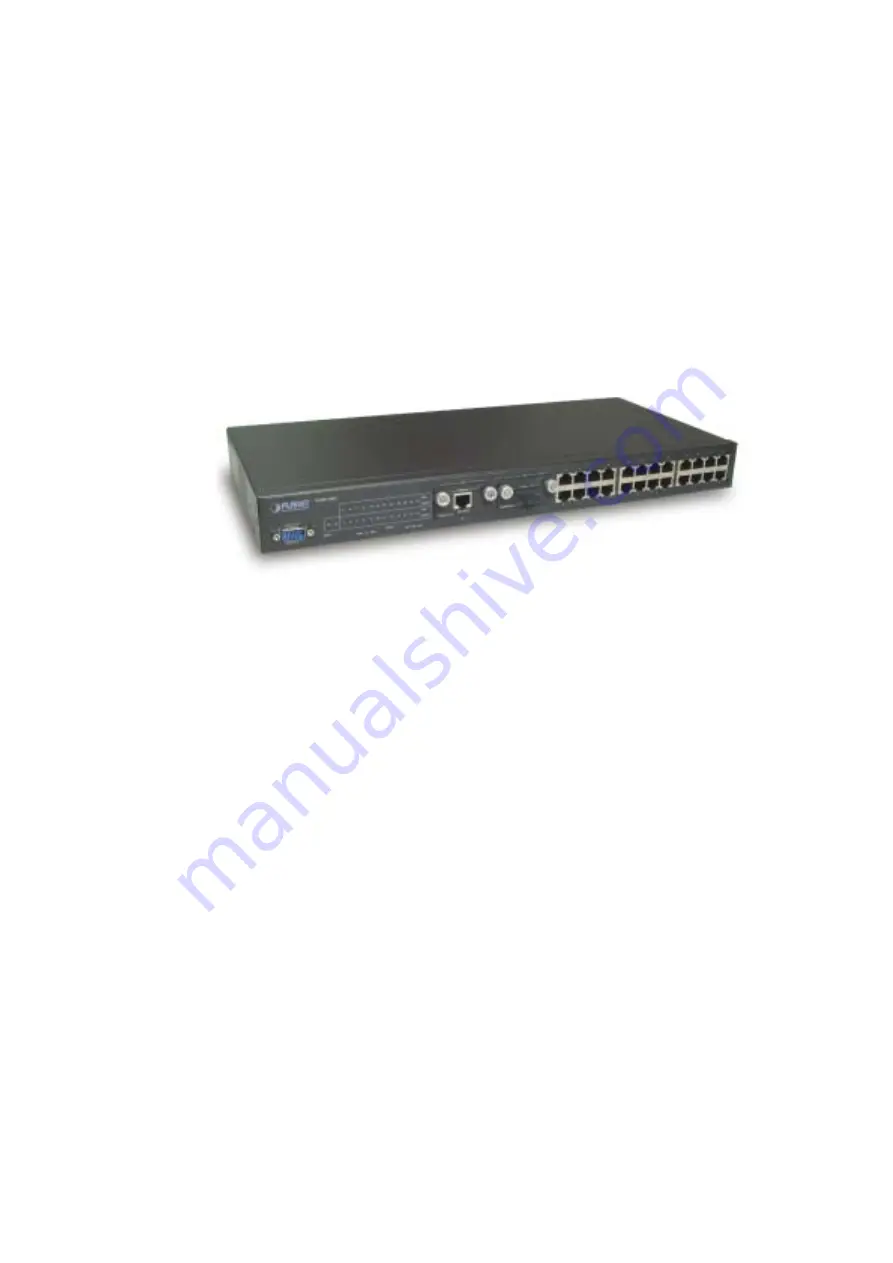
Page 8: ...nel of the SGSW 2402 Intelligent Switch consists of 24x auto sensing 10 100Mbps Ethernet RJ 45 Ports two optional expansion slots and Console port The LED Indicators are also located on the front panel of the Switch SGSW 2402 Switch front panel 2 1 1 LED indicators SGSW 2402 PWR Green Lit on Power on Lit off power off Link Green Lit on the connection is good Lit off the port is disabled or not det...
Page 9: ...or 50 125 fiber cable on 1000Base SX module 550m for 62 5 125 and 50 125 fiber cable and 10km for 9 125 fiber cable on 1000Base LX module Make sure the wiring is correct It can be used Category 3 4 5 cable in 10 Mbps operation To reliably operate your network at 100Mbps and 1000Mbps you must use an Unshielded Twisted Pair UTP Category 5 cable or better Data Grade cabling While a Category 3 or 4 ca...
Page 10: ...ice power on the device The terminal will display that it is loading the firmware Then the screen as below will show up Press Enter and input the password The default password is admin 2 5 IP Configuration Once log on to the console the Command prompt will be shown You can type help for all available commands ...
Page 11: ...h the following IP settings IP Address 192 168 0 2 Subnet Mask 255 255 255 0 Default Gateway 192 168 0 254 Press input the following command and press Enter button sys set ip 192 168 0 2 255 255 255 0 192 168 0 254 If the IP is successful configured the switch will automatically restart as the following window You can then configure the switch through its web interface ...
Page 12: ...rformed the following tasks Configure it with a valid IP address subnet mask and default gateway using an out of band serial connection For Internet Explorer 5 0 or later version user please check the Java setting below before startup 1 Click on Tools 2 Pick Internet Options 3 Select the Security tab 4 Select Local Intranet click on the icon 5 Click on Sites click Advanced and add the IP address o...
Page 13: ...sword Screen After the password is entered you will see the main menu screen Figure 3 2 The start up screen of SGSW 2402 Web Page 3 3 Port Config This section allows you to have an easy access in configuring the ports of the management Switch Notice that the Link state option indicates Up This shows that the port is connected to the network It can either be in Up Connected or Down No connection st...
Page 14: ... connected speed is 100M Only 10M broadcast data can pass through the port Port Priority In a tagged VLAN application you can specify the VLAN priority to expedite the VLAN traffic There are 8 levels of priority namely 0 1 2 3 4 5 6 and 7 in ascending priority Port VLAN ID VLAN ID is the sequence number of a VLAN The setting of the VLAN ID depends on Belongs to VLANs option Thus you should first c...
Page 15: ... only forwards traffic within its member ports For tagged VLAN each port can be a member of more than one VLAN group and it also supports priority with eight levels There is also provision for creating an untagged VLAN which support a connection with a legacy untagged port The VLAN configuration feature also allows you to build delete and view tagged untagged VLAN groups and setting priority for t...
Page 16: ...le logical link The port trunk acts as single link between switches It doesn t create a loop even though it is physically connected as such Figure 3 5 The Port Trunk config Page Port Trunking Setup Procedures Step 1 You can choose up to 4 port for Trunking by selecting as T Step 2 Click on Apply button to make the configuration effective Step 3 Click Save button to save the latest setting NOTE If ...
Page 17: ...o determine the best path between devices Therefore lower values should be assigned to ports attached to faster media and higher values assigned to ports with slower media Path cost takes precedence over port priority The default and recommended range is Ethernet 100 50 600 Fast Ethernet 19 10 60 Gigabit Ethernet 4 3 10 The allowed range is 0 65535 Priority Defines the priority for the use of a po...
Page 18: ...ome the root device Hello Time The Hello time of the Spanning Tree field shows the number of seconds between the transmissions of Spanning Tree protocol configuration messages Forward Delay The Forward Delay field shows the number of seconds a port waits before changing from its Spanning Tree Protocol learning and listening states to the forwarding state This waiting is necessary so that other swi...
Page 19: ...ng 3 8 2 Definition on IGMP v1 0 and v2 0 For IGMP v1 0 The Internet Group Management Protocol IGMP v1 0 is used by IP hosts to report their host group memberships to any immediately neighboring multicast routers IGMP is an asymmetric protocol and is specified here from the point of view of a host rather than a multicast router NOTE IGMPv1 has no leave mechanism If a host no longer wants to receiv...
Page 20: ...k on which it received the Report and sets the timer for the membership to the Group Membership Interval When a host joins a multicast group it should immediately transmit an unsolicited Version 2 Membership Report for that group in case it is the first member of that group on the network When a host leaves a multicast group if it was the last host to reply to a Query with a Membership Report for ...
Page 21: ...9 The Stack screen page Step 5 enter another unit management switch IP ex 203 70 249 154 as Slave switch Step 6 choose Stack Config Step 7 choose Enable of Stacking State and Save Figure 3 10 The Stack screen page ...
Page 22: ...gement applications To control the access of the system a list of community entries is defined Each community entry consists of a community string and its access privilege The Access privilege is either Read Only or Read Write Only SNMP messages with correct community string and allowable operation are responded by the system The community list is configurable by all management operations Only SNM...
Page 23: ...is included in the trap message When an event arises that requires a trap message to be sent it is sent to every node listed in the Trap Receiver NOTE If you are configuring slave switch s SNMP settings please reboot the switch after making any configuration Figure 3 12 The SNMP screen 3 11 RMON Statistics This function allows to display all port s RMON Statistics ...
Page 24: ...f all 26 ports some of the end nodes may need to assign to the specific port In order to fulfill this act MAC Address should be added to that particular port This is to ban other users from using the static port A port can accommodate up to 20 MAC Addresses ...
Page 25: ...you to confirm your action Step 2 Choose OK button to confirm The particular MAC Address will be successfully deleted For deleting ALL MAC Addresses Step 1 Click on Delete All button and the system will again prompt you the message as shown as above Step 2 Choose OK button to confirm All MAC Addresses will be deleted immediately 3 13 Mirror Port 3 13 1 Using Mirror Port to Monitor Traffic This fun...
Page 26: ...ess entries in the switch s forwarding table If the aging control is enabled a learned address entry not included the static entry will be removed from the forwarding table if there is no update within a pre determined period 1 128 x 5 seconds It is useful because the resource of the forwarding table is limited Enabling the aging control will not influence packets forwarding for that the packet is...
Page 27: ...trol is enabled If the aging control is disabled this step can be skipped 3 15 Address Search Host Search is for searching a host by IP or MAC address on the whole switch and getting the port number to switch the host is connected It is useful while configuring the VLAN With this function you can easily detect the port at which a host is connected to and have an idea about which ports should be in...
Page 28: ... search page 3 15 1 Host Searching Procedures Step 1 Enter the IP Address of the host Step 2 Click on Search button The result will displayed as shown If the system can not find the Host Address the following GUI will appear ...
Page 29: ...way while configuring the VLAN The system will search through the device for the port s ownership of that particular PC Figure 3 18 The MAC Address search screen MAC Address Search Procedures Step 1 Enter MAC Address in the field provided Step 2 Click on Search button If MAC Address was found by the system the result will appear as ...
Page 30: ...reen Reboot Switch The Aging Control Setup Screen Logout The Address Search Setup Screen 3 17 System Config This page allow configuring the basic switch information and IP address The configuration procedure is Step 1 Give a description for the system name and location of this switch Step 2 Key in the contact information and describe the product of the switch Step 3 Enter the IP address and Subnet...
Page 31: ...ress of the device the system will not lead you to log in the management switch web page after you have clicked Logon button Instead a page error will display on the screen state that The page cannot be displayed Don t worry What you need to do is to enter your NEW IP Address to login to the web page Figure 3 19 System Config screen 3 18 System Information System Information displays the necessary...
Page 32: ...28 Figure 3 20 The System Information 3 19 Change Password This option allows you to amend the current password ...
Page 33: ... 3 Enter the new password again for confirmation Step 4 Click on Changing Password button to active the new setting If your password is keyed correctly the system will reply you with a system message stating that your password has been changed successfully However if wrong password is entered any of the error messages shown below will appear ...
Page 34: ...d correctly 3 20 Firmware Upgrade You can simply download the newer version Firmware from www planet com tw Here you will find links that allows easy access for upgrading of future released of updated firmware Figure 3 22 The Firmware Upgrade page ...
Page 35: ...isk Upgrade Firmware Procedure Step 1 Click Browse button to select the file where you have just saved and Choose file dialog box will appear prompting you to select the file to upgrade the firmware Step 2 Click Upgrade button to start replacing the latest Firmware revision The system will prompt you reboot the management switch Step 3 Click Yes button to restart the device ...
Page 36: ...using the same or older version of the firmware the system will prompt you whether or not to use the firmware See the GUI shown below On the other hand if you choose the wrong file a system message will appear 3 21 Save Reboot The Save and Reset Settings allow you to execute the amendments or reset to the default setting of configuration ...
Page 37: ... that the profile is updated correctly 3 21 2 Backup This option allows you to backup the switch s configuration into a file To create a backup configuration Step 1 Click on the Backup button and the system will prompt you to either open the file or save it to disk Step 2 Select the radio button to Save the file to disk and click OK button ...
Page 38: ... cfg to a destination Step 3 Select a folder that you want to save the file and click SAVE button to proceed Step 4 After downloading process has completed the following GUI will appear Click Close button if you do not want to view the downloaded file ...
Page 39: ...ption allows you to restore the old configuration from your backup file Step 1 Click Browse button and select the file that you want the system to restore back the configuration Step 2 Click Restore button to start the process ...
Page 40: ...clicking this option you will restore the management switch to factory defaults And you will have to re enter all the configuration information to your network To Clear or reset the setting Step 1 Click on Clear and Reset button The system will prompt you to choose whether you really want to reset the configuration data Step 2 Click Yes button to proceed and the system will automatically reset the...
Page 41: ...37 Step 3 Click Logon button if you want to make some more changes 3 22 Message Windows Display Switch system message Figure 3 23 The Message Window page ...
Page 42: ...fect 3 24 Logout With the web browser logging out is as easy as ABC By clicking Logout button you will get a logout GUI as shown below If you need to access to the Web Page again you just need to click Logon button This is true only if you have not changed the default factory settings for the IP address of your switch Alternatively you can log in again into the web based browser via http 192 168 1...
Page 43: ...39 Figure 3 25 The Logout page NOTE If you changed a new IP Address for the management switch the system will NOT automatically changed to the new IP address after you click on the Logon button ...
Page 44: ... of Null Modem A terminal program is required to make the software connection to the device Windows Hyper Terminal program may be a good choice It can be accessed from the Start menu Click START then Programs Accessories and then Hyper Terminal MS DOS based terminal program such as PC PLUS PROCOMM can also make the connection with the device built in software The COM port should be configured as B...
Page 45: ...GSW 2402 Console Login on Screen Enter the console interface factory default console password admin or user defined password if you changed the default password using the instructions in Section 4 2 9 The Switch Management prompt in Figure 4 2 appears Figure 4 2 SGSW 2402 Console Main Screen ...
Page 46: ...Subnet Mask Default Gateway sys set name string sys set contact string sys set location string sys set password sys set link_info on off sys reset system sys reset config sys save config LOGOUT EXIT MANAGEMENT COMMANDS Logout PORT PORT MANAGEMENT COMMANDS port show port set enable port number h f 10 100 1000 A port set disable port number port set flw port number on off port set bck port number on...
Page 47: ...MANDS trunk show trunk set port1 port2 port3 port4 STP STP MANAGEMENT COMMANDS stp on off SNMP SNMP MANAGEMENT COMMANDS SNMP ON OFF STACK STACK MANAGEMENT COMMANDS stack on off 4 2 1 sys System Management Commands This menu contains system parameters to display and configure the switch to your network Menu items are Figure 4 4 SGSW 2402 sys command Screen ...
Page 48: ...his command display the system information of SGSW 2402 Figure 4 5 SGSW 2402 system information Screen 4 2 3 sys show IP This command display the network information of SGSW 2402 Figure 4 6 SGSW 2402 network information Screen ...
Page 49: ...y the MAC address of SGSW 2402 Figure 4 7 SGSW 2402 Mac address information Screen 4 2 5 sys set ip IP Address Subnet Mask Default Gateway This command allow to set the IP address Subnet Mask Gateway of SGSW 2402 Figure 4 8 SGSW 2402 network setting Screen ...
Page 50: ...llow to set the system name of SGSW 2402 Figure 4 9 SGSW 2402 system name setting Screen 4 2 7 sys set contact string This command allow to set system administrator name of SGSW 2402 Figure 4 10 SGSW 2402 system administrator name setting Screen ...
Page 51: ...SGSW 2402 Figure 4 11 SGSW 2402 system location setting Screen 4 2 9 sys set password This command allow to set the password of SGSW 2402 NOTE The new password should be an alphanumeric string of size 6 to 15 starting with a letter Figure 4 12 SGSW 2402 password setting Screen ...
Page 52: ...ts Once it is enabled it will prompt the port status on the console Or if you disable it it will not prompt the port status any more Figure 4 13 SGSW 2402 system link report setting Screen 4 2 11 sys reset system This command will reboot the SGSW 2402 Figure 4 14 SGSW 2402 reset system Screen ...
Page 53: ...his command will reboot and reset to the default mode of SGSW 2402 Figure 4 15 SGSW 2402 reset config Screen 4 2 13 sys save config This command will save the current configure of SGSW 2402 Figure 4 16 SGSW 2402 save config Screen ...
Page 54: ... logout the SGSW 2402 Figure 4 17 SGSW 2402 logout Screen 4 2 15 port Port Management Commands This menu contains system parameters to display and configure the port of the switch Menu items are Figure 4 18 SGSW 2402 port command Screen ...
Page 55: ...isplay port status of each port Figure 4 19 SGSW 2402 port statistics Screen 4 2 17 port set enable port number h f 10 100 1000 A This command allow to set the speed duplex mode of each port Figure 4 20 SGSW 2402 port set enable Screen ...
Page 56: ...4 2 19 port set flw port number on off This command allow to disable or enable flow control on each port Figure 4 22 SGSW 2402 flow control disable enable Screen 4 2 20 port set bck port number on off This command allow to disable enable Back Pressure on each port Figure 4 23 SGSW 2402 Back Pressure disable enable Screen ...
Page 57: ...iority This command allow to set the priority on each port Figure 4 24 SGSW 2402 port priority Screen 4 2 22 port set vid port number v vid This command allow to set the VLAN group and assign VLAN ID Figure 4 25 SGSW 2402 port VLAN ID Screen ...
Page 58: ...ands This menu contains system parameters to display and configure the VLAN of SGSW 2402 Menu items are Figure 4 25 SGSW 2402 VLAN command Screen 4 2 24 vlan show This command display VLAN states Figure 4 26 SGSW 2402 VLAN statics Screen ...
Page 59: ...nd assign VLAN tag and untagged Figure 4 27 SGSW 2402 VLAN setting Screen 4 2 26 vlan delete vid This command allow to delete VLAN group Figure 4 28 SGSW 2402 VLAN delete Screen 4 2 27 vlan set pri vid p priority This command allow to set VLAN priority Figure 4 28 SGSW 2402 VLAN priority Screen ...
Page 60: ...This menu contains system parameters to display and configure the trunk of this switch Menu items are Figure 4 29 SGSW 2402 Trunk command Screen 4 2 29 trunk show This command displayed the Trunk status Figure 4 30 SGSW 2402 Trunk status Screen ...
Page 61: ...up setting Screen 4 2 31 stp STP Management Commands This command allow to disable enable STP function on SGSW 2402 Figure 4 31 SGSW 2402 disable enable STP Screen 4 2 32 snmp SNMP Management Commands This command allow to disable enable SNMP function on SGSW 2402 Figure 4 32 SGSW 2402 disable enable SNMP Screen ...
Page 62: ...58 4 2 33 stack STACK Management Commands This command allow to disable enable Stack function on SGSW 2402 Figure 4 33 SGSW 2402 disable enable Stack Screen ...
Page 63: ...ble may be used even when the end station is attached via a patch panel However when attaching another switch or attaching workstations via hubs a crossover cable will need to be used Please see the following wire diagrams for examples of both cable types Figure A 1 Straight Through Cable Figure A 2 Crossover Cable ...