


21
Functions
LRP Switch
LRP Extender
LRP-822CS/LRP-1622CS
LRP-104CET
Power Input
Power cord with AC 100~240V,
50/60Hz, auto-sensing
BNC
with DC power over
coaxial input
Power Output
BNC
with DC power over coaxial
output
RJ45
with 802.3at/af PoE
output
Installation Instructions
Step 1.
Connect the LRP Switch (LRP-822CS/LRP-1622CS) and LRP Extender
(LRP-104CET) to ends of BNC terminated coaxial cable.
Step 2.
Connect 100~240V AC power cord to LRP Switch (LRP-822CS/
LRP-1622CS) power socket, then the PWR LED of LRP Switch
(LRP-822CS/LRP-1622CS) should be lit up immediately.
The LRP Managed Switch is configured
DISABLED
Long Reach PoE
function as default. So you must Enable Long Reach PoE function for
all LRP ports from WebUI.
Step 3.
After
enabling
the LRP function of LRP Switch (LRP-822CS/
LRP-1622CS) from WebUI, the PWR LED of LRP-104CET should be lit
up immediately.
Step 4.
Connect Cat5/6 UTP cable to LRP-104CET and IEEE 802.3at/af
complied PoE IP camera or PoE Wireless AP.
Note
Additional advanced settings for the LRP Switch (LRP-822CS /
LRP-1622CS) can be downloaded from the PLANET website or
contact the PLANET support team.
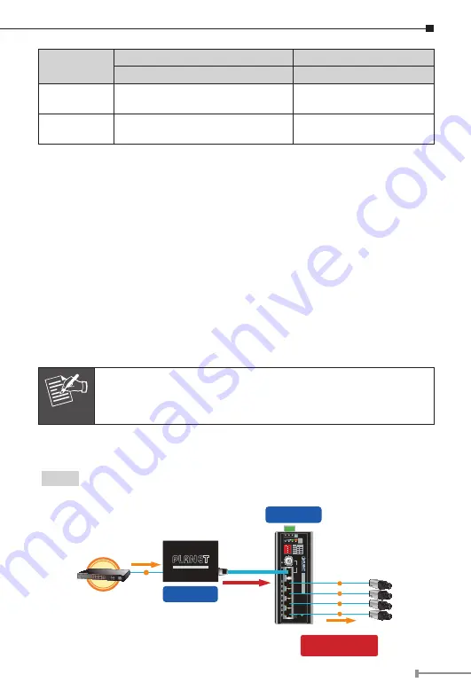
6.2 Applications of LRP-101U-KIT with UTP/Twisted-pair Cable
Type 1
LRP-101UH with PoE power input and LRP-104CET with PoE power
output
802.3af/802.3at PoE
PoE IP Camera
LRP-104CET
Long Reach PoE Extender
P1
P2 Fault
PWR
LNK
LRP IN
4
3
2
1
LRP-104CET
Ext.
PWR
10W 20W 30W 40W
PoE
Power
Usage
ACT
LNK
PoE In-use
ON
ON
ON
ON
OFF
OFF
OFF
OFF
1
Port
PoE
2
3
4
Long Reach PoE
Extender
1
2
3
4
O
FF
802.3af / 802.3at
PoE Switch
PoE
Cat5e/6
PoE
PoE
PoE
PoE
PoE
Remote LRP Power over UTP
Power over UTP
LRP-101UH
Long Reach PoE Injector
Long Reach Power over Ethernet
PoE Power Budget
20 watts (max.)