50
3.2.3 Adjusting to Video Sources
Video adjustments are quite a bit like the controls on a television receiver.
Adjusting the picture
1. Select a video source in the Picture menu. When
the VIM option is installed (Video Input Module)
Margay has available
a. one composite video,
b. one S-Video, and
c. one component (YPbPr) input.
2. Press
LEVEL
on the remote.
These controls are also used for analog sources when
you chose YPbPr Colorspace.
Now you have two choices.
• Adjust using any picture from the video source.
• Adjust using a standard color bar pattern from the
source.
Adjusting with any picture
This procedure must be done
after
you adjust color
balance (page 52).
1. Choose pictures that have blacks and whites rep-
resented as well as a variety of colors.
2. Adjust Contrast, Brightness, Saturation and Hue
on
one
Margay until it looks satisfactory.
3. Adjust all the other Margays in the wall so they
have the same values for Contrast, Brightness,
Saturation and Hue as the first Margay.
Adjusting with color bars
1. If possible, use a color bar pattern from the video
source you will use for the program material. You
cannot use the color bar from the Test Patterns
menu.
2. In the Picture menu, check Blue Only. You should
see only the alternate color bars, all of them blue.
3. Adjust Saturation to make the outer two color
bars match. Match them in brightness; they will
already match in color.
4. Adjust Hue to make the inner two color bars
match.
5. Uncheck Blue Only
When a video source is selected, Auto Setup Options is
not available. Adjustments must be made manually.
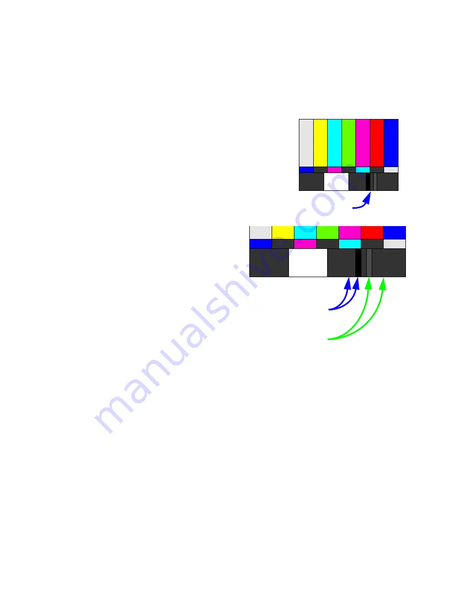
6. If the color bar pattern has a pluge, you can use it
to adjust Brightness.
Pluge
Adjust Brightness so you
cannot
see the different between these
two marks,
but you
can
see the difference
between these two marks.
Summary of Contents for WN-5040-720
Page 1: ...WN 5040 720 User Guide...
Page 2: ......
Page 3: ...i WN 5040 720 Margay 50 Display Wall Unit User Guide 020 0548 00B 29 March 2007...
Page 6: ...iv...
Page 7: ......
Page 14: ...5...
Page 17: ...6...
Page 20: ...9...
Page 24: ...13...
Page 30: ...19...
Page 32: ...21 Electronics module as seen from the front The electronics module door is open...
Page 34: ...23 In Out...
Page 36: ...25...
Page 38: ...27 AC power in and out 1 4 5 3 2 6 No more than 4 115 VAC...
Page 40: ...29...
Page 51: ...40...
Page 54: ...43...
Page 56: ...45...
Page 58: ...47...
Page 66: ...55...
Page 70: ...59...
Page 72: ...61...
Page 74: ...63 ENTER ENTER...
Page 77: ...66...
Page 80: ...69...
Page 82: ...71...
Page 84: ...73...
Page 86: ...75...
Page 95: ...84...
Page 115: ...104 Diagnostics RS232 RS485 Status...
Page 116: ...105 Diagnostics Test Patterns...
Page 117: ...106 Diagnostics Setup Summary...
Page 128: ...117 Starts scanning the input con nectors for the next available source...
Page 131: ...120 7 3 Drawings All dimensions are in inches...
Page 132: ...121...
Page 133: ...122...
Page 134: ...123...
Page 140: ...129...
Page 144: ...133...


