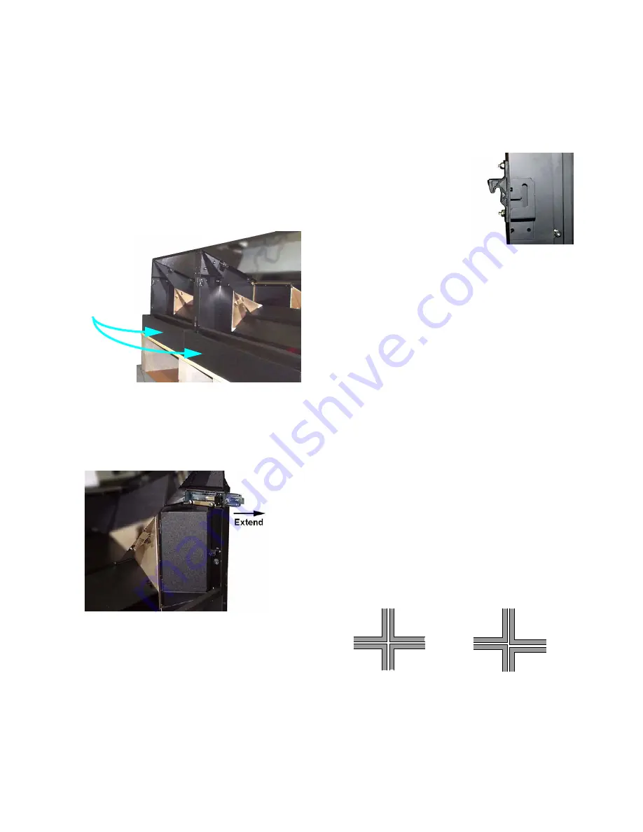
2.6 Installing and Removing Screens
32
2.6.1 Installing the Screens
Start in the middle of the bottom row and work outward and upward.
First
1. Be sure the wall of Margays is straight and the
corners are square. Measure the diagonals of the
whole wall. If the diagonals are equal, the wall is a
perfect rectangle.
2. The screen supports should be installed on the
bottom row of Margays.
Then
3. Start in the
middle of the bottom row
and install
that screen.
a. Pull the screen rails all the way out on both
sides of the Margay chassis.
b. The screen rails have a large pin and the
screens have an L-shaped slot.
c. With one person holding each side of the
screen, hang the screen on the rail so the pin
goes into the slot.
4. Slide the screen closed, lifting it slightly so the
screen won’t scrape on the screen support below.
Next
5. Install the screens to the left and right of the cen-
ter to complete the bottom row.
a. After you add a screen, press it toward the cen-
ter.
6. Install the screens above the center screen.
a. Left each screen and you press it in so it doesn’t
scrape on the screen below.
b. Continue until you reach the top.
7. Check the line of this bottom row of screens. If
they are not straight, use
shims
on the top of the
screen support until the screens are straight.
8. Complete the second row, working outward and
pressing the screens inward after they are pressed
home.
9. Working upward and outward, finish all the rows.
Final adjustment
Check all the screens for alignment with each
other. The lines between screens should form straight
lines where they intersect.
Screen supports
The four corners
should meet like
this …
… not like this.
Summary of Contents for WN-5040-720
Page 1: ...WN 5040 720 User Guide...
Page 2: ......
Page 3: ...i WN 5040 720 Margay 50 Display Wall Unit User Guide 020 0548 00B 29 March 2007...
Page 6: ...iv...
Page 7: ......
Page 14: ...5...
Page 17: ...6...
Page 20: ...9...
Page 24: ...13...
Page 30: ...19...
Page 32: ...21 Electronics module as seen from the front The electronics module door is open...
Page 34: ...23 In Out...
Page 36: ...25...
Page 38: ...27 AC power in and out 1 4 5 3 2 6 No more than 4 115 VAC...
Page 40: ...29...
Page 51: ...40...
Page 54: ...43...
Page 56: ...45...
Page 58: ...47...
Page 66: ...55...
Page 70: ...59...
Page 72: ...61...
Page 74: ...63 ENTER ENTER...
Page 77: ...66...
Page 80: ...69...
Page 82: ...71...
Page 84: ...73...
Page 86: ...75...
Page 95: ...84...
Page 115: ...104 Diagnostics RS232 RS485 Status...
Page 116: ...105 Diagnostics Test Patterns...
Page 117: ...106 Diagnostics Setup Summary...
Page 128: ...117 Starts scanning the input con nectors for the next available source...
Page 131: ...120 7 3 Drawings All dimensions are in inches...
Page 132: ...121...
Page 133: ...122...
Page 134: ...123...
Page 140: ...129...
Page 144: ...133...


