
ATTENTION
Wetting the Pump. Before starting the pump, wet the inside of the pump body with oil throu-
gh the inlet and outlet openings.
S
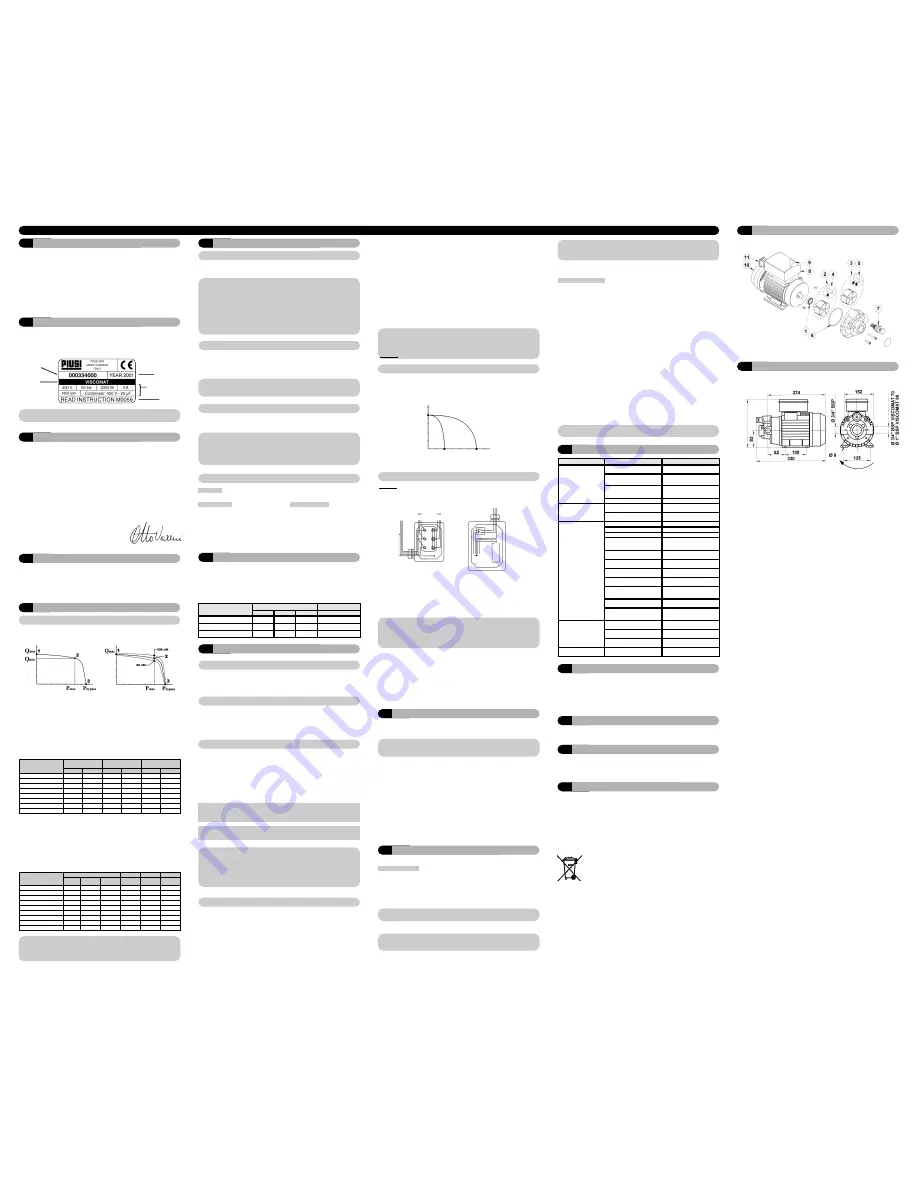
DIMENSIONS
ENGLISH
A
Index
B
Machine and Manufacturer Identification
C
Declaration of Conformity
D
Machine Description
E
Technical Specifications
E1
Performance Specifications
E2
Electrical Specifications
F
Operating Conditions
F1
Environmental Conditions
F2
Electrical Power Supply
F3
Working Cycle
F4
Fluids Permitted / Fluids Not Permitted
G
Moving and Transport
H
Installation
H1
Disposing of the packing material
H2
Preliminary Inspection
H3
Mechanical Installation
H4
Hydraulic Connection
H5
Considerations Regarding Delivery
and Suction Lines
H6
Maximum pressure decrease
H7
Electrical Connections
I
Initial Start-Up
L
Daily Use
M
Problems and Solutions
N
Maintenance
O
Noise Level
P
Disposal of Contaminated Materials
Q
Disposal
R
Exploded Diagrams
S
Dimensions
MODEL:
VISCOMAT
MANUFACTURER:
PIUSI SPA
46029 SUZZARA (MN)
IDENTIFICATION PLATE
(EXAMPLE WITH THE FIELDS IDENTIFIED):
ATTENTION
Always check that the revision level of this manual coincides with what is shown on the identification plate.
ATTENTION
The power absorbed by the pump depends on the functioning point and the viscosity of the
oil being pumped.
The data for MAXIMUM CURRENT provided in the Table refer to pumps functioning at the point
of maximum compression P max, with oils of a viscosity equal to approximately
500 cSt.
ENGLISH
ENGLISH
A
INDEX
B
MACHINE AND MANUFACTURER IDENTIFICATION
C
DECLARATION OF CONFORMITY
F
OPERATING CONDITIONS
D
MACHINE DESCRIPTION
PUMP:
Self-Priming, volumetric, rotating electric vane pump equipped with by-pass valve.
MOTOR:
Asynchronous motor, single-phase or three-phase, 2 or 4 pole, closed type
(Protection class IP55 according to regulation EN 60034-5-86), self-ventilating,
flange-mounted directly to the pump body.
E
TECHNICAL SPECIFICATIONS
The performance data provided for the various
pump models of the VISCOMAT family can be
illustrated with curves that show the relationship
between the
flow rate
supplied and the
back
pressure
that the pump must overcome.
Diagram
"A"
illustrates a
flow rate/back
pressure curve
typical of all of the pumps in the
VISCOMAT family.
E1 PERFORMANCE SPECIFICATIONS
Point "1" is the point at which the pump is
functioning with practically no back pressure,
in which case the pump supplies the maxi-
mum flow rate
(Q max).
Point "2" is the functioning point characteri-
zed by the maximum back pressure
(P max)
at which the pump supplies the minimum
flow rate
(Q min).
When the back pressure exceeds the value
P
max,
thanks to the special design of the by-
pass, there is a sudden opening of the by-
pass, with a consequent sudden reduction of
the flow rate supplied.
At flow rate zero (point "3") the entire flow rate
supplied by the pump is recirculated in the
by-pass, and the pressure in the delivery line
reaches the value of
P By-pass.
VISCOMAT pumps can, therefore, function in
the face of any back pressure between zero
and
P max
, supplying a flow rate varying little
as a function of the back pressure between
the values of
Q max
and
Q min
.
The values for
Q min
,
Q max
,
P max
and
P by-
pass
are provided for each model of pump in
the Table below:
VISCOMAT pumps can pump oils of very dif-
ferent viscosities, within the limits indicated in
the TECHNICAL SPECIFICATIONS, without
requiring any adjustment of the by-pass.
The characteristic flow rate/back pressure
curve illustrated in diagram
"A"
relates to
functioning with oil of
a viscosity equal to
approximately 110cSt
(comparable, for exam-
ple, to oil SAE W80 at a temperature of 22°C).
As the viscosity of the oil varies, the variation
in the pump's performance will be more
noticeable the greater the back pressure
against which the pump is working.
Diagram
"B"
illustrates how the characteristic
curve changes in the case of the maximum
and minimum viscosities (respectively equal
to 50 cSt and 500 cSt), showing that, at the
maximum working back pressure (Pmax),
the flow rate Q min suffers a
variation of
between 10% and 15%
with respect to the
value relative to a viscosity of 110 cSt.
F1 ENVIRONMENTAL CONDITIONS
TEMPERATURE:
min. -10
o
C / max +60
o
C
RELATIVE HUMIDITY:
max. 90%
F2 ELECTRICAL POWER SUPPLY
ATTENTION
The temperature limits shown apply to the pump components and must be respected to
avoid possible damage or malfunction.
It is understood, nevertheless, that for a given oil, the real functioning temperature range also
depends on the variability of the viscosity of the oil itself with the temperature. Specifically:
• The minimum temperature allowed (-10°C) could cause the viscosity of some oils to
greatly exceed the maximum allowed, with the consequence that the static torque
required during the starting of the pump would be excessive, risking overload and
damage to the pump.
• The maximum temperature allowed (+60°C) could, on the other hand, cause the viscosity
of some oils to drop well below the minimum allowed, causing a degradation in
performance with obvious reductions in flow rate as the back pressure increases.
Depending on the model, the pump must be fed by
three-phase or single-phase alternating current whose
nominal values are those indicated in the Table of
paragraph E2 - ELECTRICAL SPECIFICATIONS.
The maximum acceptable variations from the
electrical parameters are:
Voltage:
+/-5% of the nominal value
Frequency:
+/- 2% of the nominal value
ATTENTION
Power from lines with values outside the indicated limits can damage the electrical
components.
F3 WORKING CYCLE
The motors are intended for continuous use.
Under normal operating conditions they can function continuously with no limitations.
ATTENTION
Functioning under by-pass conditions is only allowed for brief periods of time (2-3
minutes maximum).
Whenever a particular installation carries the risk of functioning in by-pass mode for longer
periods of time,
it is necessary that the by-passed flow not be recirculated inside the
pump, but be returned to the suction tank.
F4 FLUIDS PERMITTED / FLUIDS NOT PERMITTED
G
MOVING AND TRANSPORT
Given the limited weight and size of the
pumps (see paragraph R - DIMENSIONS
AND WEIGHTS),
moving the pumps does
not require the use of lifting devices.
The pumps were carefully packed before
shipment.
Check the packing material on delivery and
store in a dry place.
H
INSTALLATION
H1 DISPOSING OF THE PACKING MATERIAL
The packing material does not require
special precautions for its disposal, not being
in any way dangerous or polluting.
Refer to local regulations for its disposal.
H2 PRELIMINARY INSPECTION
• Check that the machine has not suffered
any damage during transport or storage.
• Clean the inlet and outlet openings,
removing any dust or residual packing
material.
• Make sure that the motor shaft turns
freely.
• Check that the electrical specifications
correspond to those shown on the
identification plate.
If this phase is excessively prolonged,
stop the pump
and verify:
• that the pump is not running completely
"dry"
• that the suction hose guarantees against
air infiltration and is correctly immersed in
the fluid to be drawn
• that any filters installed are not blocked
• that the delivery hose allows for the easy
evacuation of the air.
• that the priming height is not greater than
2,5 meters
When priming has occurred, after
reattaching the delivery gun,
verify that the
pump is functioning within the anticipated
ranges
, possibly checking:
1) that under conditions of maximum back
pressure, the power absorption of the
motor stays within the values shown on
the identification plate
2) that the suction pressure does not exceed
the limits indicated in paragraph
H5 - CONSIDERATIONS REGARDING
SUCTION & DELIVERY LINES
3) that the back pressure in the delivery line does
not exceed the values indicated in paragraph
H5 - CONSIDERATIONS REGARDING SUC-
TION & DELIVERY LINES.
For a complete and proper verification of points
2) and 3), the installation of vacuum and air
pressure gauges at the inlet and outlet of the
pump is recommended.
ENGLISH
L
DAILY USE
No particular preliminary operation is required for every day use of VISCOMAT pumps.
MANUAL OPERATION
• Before starting the pump, make sure that
the ultimate shut-off device (delivery
nozzle or line valve) is closed.
If the delivery has no shut-off device (free
delivery) make sure that it is correctly
positioned and appropriately attached to
the delivery tank.
• turn the on-switch present on some pump
models (single-phase) or the start/stop
switch installed on the electrical power
line.
• make sure that the tank is filled with a
quantity of oil greater than the quantity to
be supplied (running dry could damage
the pump).
ATTENTION
Never start the pump by simply inserting the plug in the outlet
• Open the delivery valve or activate the delivery gun, gripping it securely.
ATTENTION
Fluid exits at high pressure from a delivery gun fed by a VISCOMAT pump.
Never point the outlet of the gun towards any part of the body.
• Close the delivery gun or the line valve to stop delivery. The pump will immediately enter
by-pass mode.
ATTENTION
Running in by-pass mode with the delivery closed is only allowed for brief periods (2 to 3 minutes
maximum).
When the thermo-protector trips, turn-off the electric power and wait for the motor to cool.
• Stop the pump.
AUTOMATIC OPERATION
In certain applications it can be advanta-
geous to provide for the
automatic
starting/stopping of the pump by means of
a pressure switch that monitors the
pressure of the delivery line.
The functional logic of this type of installation
is as follows:
• the pump is stopped, the delivery gun is
closed and the delivery line is under
pressure.
• the delivery gun is then opened, with the
consequent sudden lowering of pressure
in the delivery line.
• the pressure switch, at the moment that
the pressure drops below the value
"Pm"
automatically starts the pump allowing
delivery.
• during delivery the pump delivers against
a back pressure that, depending on the
conditions of the delivery line, could turn
out to be higher or lower than the
pressure
"Pm"
.
• at the moment the delivery gun is closed,
the pressure will increase rapidly and the
pressure switch, at the moment in which
the pressure exceeds the value
"Pa"
will
automatically stop the pump.
The values of
"Pa"
and
"Pm"
are characteristics of the pressure switch used and are often
adjustable within a certain range.
For the safe and proper functioning of the pump in these types of applications it is
absolutely indispensable to make sure that:
•
"Pa" is sufficiently lower than the
by-pas pressure,
to assure that the pump
will stop as soon as the gun is closed and
that the pump will not run a long time in
by-pass mode.
•
"Pm" is several bar lower than "Pa"
to
avoid the pump starting when not wanted
due to small pressure drops not caused
by opening the gun.
•
the foot valve guarantees an effective
seal
, to avoid frequent unwanted cycling
on and off caused by its leakage.
• whenever the system is entirely
composed of metal tubing, or, at any rate,
of highly rigid tubing,
one should
consider installing an accumulator
capable of preventing small leaks (from
the foot valve, for example) from causing
a pressure drop sufficient to automatically
start the pump.
ATTENTION
Failure to comply with the above can damage the pump.
N
MAINTENANCE
• On a weekly basis, check that the tubing
joints have not loosened, to avoid any
leakage.
• On a monthly basis, check the pump
body and keep it clean of any impurities.
• On a monthly basis check and clean the
filters placed at the pump inlet.
• On a monthly basis, check that the
electric power supply cables are in good
condition.
VISCOMAT series pumps are designed and constructed to require a minimal amount of
maintenance.
O
NOISE LEVEL
Under normal operating conditions noise
emission for all models does not exceed the
value of
70 dB "A" at a distance of 1 Meter
from the electric pump.
P
DISPOSING OF CONTAMINATED MATERIALS
In the case of maintenance or destruction of
the machine, do not disperse contaminated
parts into the environment.
Refer to local regulations for their proper disposal.
M
PROBLEMS AND SOLUTIONS
R
EXPLODED DIAGRAMS
Problems
Possible cause
Corrective action
THE MOTOR IS NOT
TURNING
Lack of electric power
Check the electrical connections
and the safety systems.
Rotor jammed
Check for possible damage or
obstruction of the rotating
components.
The motor protecting thermal
switch has tripped
Wait until the motor cools,
verify that it starts again, look
for the cause of overheating
Motor problems
Contact the Service Department
THE MOTOR TURNS
SLOWLY WHEN
STARTING
Low voltage in the electric power line
Bring the voltage back within the
anticipated limits
Excessive oil viscosity
Verify the oil temperature and warm
it to reduce the excessive viscosity
LOW OR NO FLOW
RATE
Low level in the suction tank
Refill the tank
Foot valve blocked
Clean and/or replace the valve
Filter clogged
Clean the filter
Excessive suction pressure
Lower the pump with respect to
the level of the tank or increase
the cross-section of the tubing
High loss of head in the delivery cir-
cuit (working with the by-pass open)
Use shorter tubing or of greater
diameter
By-pass valve blocked
Dismantle the valve, clean
and/or replace it
Air entering the pump or the
suction tubing
Check the seals of the
connections
Low rotation speed
Check the voltage at the pump.
Adjust the voltage and/or use
cables of greater cross-section
The suction tubing is resting
on the bottom of the tank
Raise the tubing
Excessive oil viscosity
Verify the oil temperature and
warm it to reduce the
excessive viscosity
INCREASED PUMP
NOISE
Cavitation occurring
Reduce the suction pressure
(see paragraph H5)
Irregular functioning of the
by-pass
Dispense fuel until the air is
purged from the by-pass system
LEAKAGE FROM THE
PUMP BODY
Damage to the mechanical
seal
Check and replace the
mechanical seal
PRODUCT
CODE
MODEL
PRODUCTION
YEAR
TECHNICAL
SPECIFICATIONS
MANUAL
PERMITTED:
• OIL with a VISCOSITY from 50 to 500 cSt (at working temperature)
NOT PERMITTED:
RELATED DANGERS:
• GASOLINE
• FIRE - EXPLOSION
• INFLAMMABLE LIQUIDS with PM < 55°C
• FIRE - EXPLOSION
• WATER
• PUMP OXIDATION
• FOOD LIQUIDS
• CONTAMINATION OF THE SAME
• CORROSIVE CHEMICAL PRODUCTS
• PUMP CORROSION
INJURY TO PERSONS
• SOLVENTS
• FIRE - EXPLOSION
DAMAGE TO GASKET SEALS
A narrowing in the suction tubing
Use tubing suitable for working
under suction pressure
H4 HYDRAULIC CONNECTION
• Make sure that the hoses and the suction
tank are free of dirt and filing residue that
might damage the pump and
accessories.
• Always install a metal mesh filter in the
suction hose.
• Before connecting the delivery hose,
partially fill the pump body with oil to
avoid the pump running dry during the
priming phase.
• When connecting pump models
furnished with BSP threading (cylindrical
gas) do not use joints with a conical
thread.
• Excessive tightening of these could cause
damage to the pump openings.
SUCTION HOSE
- Minimum nominal diameter:
1"
- Nominal recommended pressure:
10 bar
- Use tubing suitable for functioning under suction pressure.
DELIVERY HOSE
- Minimum nominal diameter:
3/4"
- Nominal recommended pressure:
30 bar
ATTENTION
The use of hoses and/or line components that are inappropriate for use with oil or have
inadequate nominal pressures can cause damage to objects or people as well as pollution.
The loosening of connections (threaded connections, flanges, gasket seals) can likewise
cause damage to objects or people as well as pollution.
Check all of the connections after installation and on a regular on-going basis with
adequate frequency.
H5 CONSIDERATIONS REGARDING DELIVERY AND SUCTION LINES
DELIVERY
The choice of pump model to use should be
made keeping in mind the viscosity of the oil to
be pumped and the
characteristics of the
system attached to the delivery of the pump.
The combination of the oil viscosity and the
characteristics of the system could, in fact,
create back pressure
greater than the
anticipated maximums
(equal to
P max
), so
as to cause the (partial) opening of the pump
by-pass with a consequent noticeable
reduction of the flow rate supplied.
In such a case, in order to permit the correct
functioning of the pump equal to the
viscosity of the oil being pumped,
it will be
necessary to reduce resistance in the
system by employing shorter hoses
and/or of larger diameter.
On the other hand, if the system cannot be
modified it will be necessary to select a
pump model with a higher
P max.
SUCTION
VISCOMAT series pumps are characterized
by excellent suction capacity.
In fact, the characteristic flow rate/back
pressure curve remains unchanged even at
high pump suction pressure values.
In the case of oils with viscosity not greater
than
100 cSt
the suction pressure can reach
values on the order of
0.7 - 0.8 bar
without
compromising the proper functioning of the
pump.
Beyond these suction pressure values,
cavitation phenomena
begin as
evidenced
by accentuated running noise
that over
time can cause pump damage, not to
mention a degradation of pump performance.
As viscosity increases, the suction pressure
at which cavitation phenomena begin
decreases.
In the case of oils with viscosities equal to
approximately
500 cSt
, the suction pressure
must not exceed values of the order of
0,3 -0,5 bar
to avoid triggering cavitation
phenomena.
The
values indicated
above refer to the
suction of oil that is substantially free of air.
If the oil being pumped is mixed with air,
the cavitation phenomena can begin at
lower suction pressures.
In any case, for as much as was said above,
it is important to guarantee low suction
pressures
(short hoses and possibly of larger
diameter than the inlet opening of the pump,
fewer curves, filters of wide cross-section and
kept clean).
ATTENTION
It is a good system practice to immediately install vacuum and air pressure gauges at
the inlets and outlets of the pump which allow verification that operating conditions are
within anticipated limits.
To avoid emptying the suction hose when the pump is turned off, the installation of a
foot valve
is recommended.
The
MINIMUM recommended
characteristics for hoses are as follows:
H7 ELECTRICAL CONNECTIONS
All motors
come with a short cable used for
production testing.
To connect the motor to the line, open the
terminal strip cover, remove the above
mentioned cable and connect the line accor-
ding to the following chart.
Single-phase motors are supplied with a
bipolar switch and capacitors wired and
installed inside the terminal strip box (see
chart).
The capacitor characteristics are those
indicated on the pump label.
ATTENTION
Pumps are supplied without electrical safety devices such as fuses, motor protectors, and
systems to prevent accidental restarting after periods of power failure or any other kind.
It is the installer's responsibility to carry out the electrical connection with respect to the
applicable regulations.
• During installation and maintenance
make sure that power to the electric lines
has been turned off.
• Employ cables characterized by
minimum cross-sections, rated voltages
and installation type adequate to the
characteristics indicated in paragraph
E2 - ELECTRICAL SPECIFICATIONS and
the installation environment.
• For three-phase motors, ascertain the
correct rotation direction by referring to
paragraph R - DIMENSIONS AND WEIGHTS.
• All motors are equipped with a ground
terminal to connect to the ground line of
the electrical network.
• Always close the cover of the terminal
strip box before turning on the electric
power, after checking the integrity of the
gasket seals that ensure protection grade
IP55.
Comply with the following (not exhaustive) instructions to ensure a proper electrical connection:
I
INITIAL START-UP
VISCOMAT series pumps are self-priming
and, therefore, able to draw oil from the tank even
when the suction hose is empty on start-up. The priming height (distance between the surface
of the oil and the inlet opening) must not exceed 2,5 meters.
The priming phase may last from several seconds to a few minutes,
depending on the
characteristics of the system.
THREE-PHASE
AC LINE
SINGLE-PHASE
TO MOTOR
CAPACITOR
Presence of air in the oil
Wait for the oil in the tank to
settle
VISCOMAT MODEL
PACKING SIZE
SINGLE-PHASE 70
180
A (mm)
350
B (mm)
240
H (mm)
14.3
THREE-PHASE 70
180
350
240
12.8
THREE-PHASE 90
180
350
240
15
(Kg)
TOTAL WEIGHT
TO
MOTOR
Flow rate
[Q]
l/min
Back pressure
[P] bar
Diagram “A”
Flow rate
[Q]
l/min
Back pressure
[P] bar
Diagram “B”
230 single-phase
195 three-phase
direction of rotation
The switch has the function of
starting/stopping the pump and cannot in
any way replace the main power switch
required by the applicable regulations.
H6 MAXIMUM PRESSURE DECREASE
VISCOMAT series pumps are equipped with an
adjusting screw to adjust the by-pass valve
pressure (pos. 10 in the exploded view).
The screw is pre-set in the factory for operating at
a maximum pressure that is equal to the
maximum counter-pressure conditions indicated
in the table under paragraph E1 - Performance
specifications.
Should it be necessary to decrease the
maximum pressure, unscrew the adjusting screw
until you reach the desired value.
The flow rate curve will be modified as follows:
As a result, plant specifications being equal,
the flow rate of the pump will be decreased
due to the earlier opening of the by-pass
valve.
Flow rate (l/min)
1-2
6
(bar)
Adjusting
screw
screwed
Adjusting
screw
unscrewed
PUMP MODEL
ELECTRICAL POWER
POWER
CURRENT
SPEED
Current
Voltage
(V)
Frequency
(Hz)
Rated
(Watt)
Maximum
(Amp)
Rated
(rpm)
VISCOMAT 70 M
AC
230
50
750
4,6
1400
VISCOMAT 70 T
AC
400
50
750
2,2
1450
VISCOMAT 90 T
AC
400
50
2000
5
1450
VISCOMAT 70 100/50
AC
100
50
900
10,5
1450
VISCOMAT 70 100/60
AC
100
50
1100
13
1700
VISCOMAT 70 110/50
AC
110
50
1200
12,7
1450
VISCOMAT 70 110/60
AC
110
50
1200
12,6
1700
VISCOMAT 90 230/50
AC
230
50
1200
6
1400
VISCOMAT 90 230/60
AC
230
60
1550
7,7
1650
PUMP MODEL
BY PASS
Condition
Max. back
pressure condition
Max. flow rate
condition
D (l/min)
P (bar)
D (l/min)
P (bar)
D (l/min)
P (bar)
VISCOMAT 70 M
0
7,5
26
6
30
1
VISCOMAT 90 T
0
6
50
5
55
1
VISCOMAT 70 100/50
0
6,5
26
4,5
30
1
VISCOMAT 70 100/60
0
5
26
3,5
36
1
VISCOMAT 70 110/50
0
7,5
26
6
30
1
VISCOMAT 70 110/60
0
5
26
3,5
36
1
VISCOMAT 90 230/50
0
6,5
35
2,5
40
1
VISCOMAT 90 230/60
0
7,5
40
3
47
1
DECLARATION OF INCORPORATION
The undersigned
PIUSI S.p.A.
Via Pacinotti, Z.I. Rangavino
46029 Suzzara (Mantova) – Italy
Declares under its own responsibility that the machine:
VISCOMAT
described below:
Machine for transferring lubricant oil
is manufactured to be incorporated into a machine or to be assembled with other machinery to
build a machine according to the Machine Directive 98/37/CE.
Moreover, we declare that the machinery cannot be put into operation until the machine in
which it will be incorporated and of which it will become a component, has been identified and
its compliance with the Machine Directive 98/37/CE has been declared.
Suzzara 01.09.2005
________________________
OTTO VARINI, Chairman
The components must be given to companies that specialise in the disposal and recycling of
industrial waste and, in particular, the DISPOSAL OF PACKAGING.
The packaging consists of biodegradable cardboard which can be delivered to companies for
normal recycling of cellulose.
DISPOSAL OF METAL COMPONENTS
The metal components, both painted and stainless steel, are usually recycled by companies
that are specialised in the metal-scrapping industry.
DISPOSAL OF ELECTRIC AND ELECTRONIC COMPONENTS:
these have to be disposed by companies that are specialised in the disposal of electronic com-
ponents, in accordance with the instructions of 2002/96/EC (see text of Directive below).
ENVIRONMENTAL INFORMATION FOR CUSTOMERS IN THE EUROPEAN UNION
European Directive 2002/96/EC requires that the equipement bearing this sym-
bol on the product and/or its packaging must not be disposed of with unsorted
municipal waste. The symbol indicates that this product should be disposed of
separately from regular household waste streams.It is your responsibility to
dispose of this and other electric and electronic equipment via designated col-
lection facilities appointed by the government or local authorities.
DISPOSAL OF OTHER PARTS:
The disposal of other parts such as pipes, rubber seals, plastic components and cables should
be entrusted to companies that special in the disposal of industrial wate.
Q
DISPOSAL


