Pittsburgh Automotive 61600 Owner'S Manual & Safety Instructions Download Page 5

Page 5

For technical questions, please call 1-888-866-5797.

Item 61600

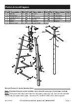
13.  Fully tighten Bolts (12) and Nuts (13) 

securing the Legs (8), Braces (9,16), 

Connectors (15), and Lower Flange of 

the Column (7), left slightly loose for 

assembly purposes in Steps 1-11.

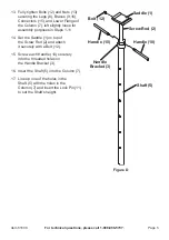
14.  Set the Saddle (1) on top of 

the Screw Rod (2) and attach 

it securely with a Bolt (12).

15.  Screw each Handle (10) securely 

into the threaded holes on 

the Handle Bracket (3).

16.  Insert the Shaft (5) into the Column (7).

17.  Line up one of the holes in the 

Shaft (5) with the holes in the 

Column (7) and insert the Lock Pin (11) 

to set the Shaft’s height.

Saddle (1)

Bolt (12)

Handle (10)

Handle (10)

Handle 

Bracket (3)

Shaft (5)

Screw Rod (2)

Figure D 

Summary of Contents for 61600

Page 1: ...ence 22e When unpacking make sure that the product is intact and undamaged If any parts are missing or broken please call 1 888 866 5797 as soon as possible Copyright 2022 by Harbor Freight Tools All...

Page 2: ...ged on an automotive lift 11 Do not use for aircraft purposes 12 Inspect before every use do not use if parts are loose or damaged 13 Be aware of dynamic loading Sudden load movement may briefly creat...

Page 3: ...Set the three longer Bolts aside before assembly for use in step 12 on page 4 Unless otherwise explained assemble parts using Bolts 12 Washers 14 and Nuts 13 Note For Steps 1 11 leave the Bolts 12 an...

Page 4: ...Connectors with their short ends horizontal Legs 8 Connectors 15 Upper Braces 16 Lower Braces 9 Figure B 10 Set the Column 7 with its Upper and Lower Flange in place on the assembled base as shown Mak...

Page 5: ...in Steps 1 11 14 Set the Saddle 1 on top of the Screw Rod 2 and attach it securely with a Bolt 12 15 Screw each Handle 10 securely into the threaded holes on the Handle Bracket 3 16 Insert the Shaft 5...

Page 6: ...o wobble If necessary tighten Handles Lock Pin Saddle Shaft Handle PLEASE READ THE FOLLOWING CAREFULLY THE MANUFACTURER AND OR DISTRIBUTOR HAS PROVIDED THE PARTS LIST AND ASSEMBLY DIAGRAM IN THIS DOCU...

Page 7: ...2 11 Lock Pin 1 12 Bolt M10X20 19 Part Description Qty 13 Nut M10 18 14 Flat Washer 18 15 Connector 3 16 Upper Brace 3 17 Bearing 1 16 15 12 11 10 1 3 4 2 5 12 17 14 13 9 6 7 8 Record Product s Serial...

Page 8: ...amages so the above limitation of exclusion may not apply to you THIS WARRANTY IS EXPRESSLY IN LIEU OF ALL OTHER WARRANTIES EXPRESS OR IMPLIED INCLUDING THE WARRANTIES OF MERCHANTABILITY AND FITNESS T...

Reviews: