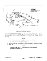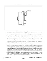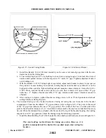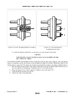
3. Remove the inspection hole plug from the magneto. Turn the magneto coupling until the painted
chamfered tooth on the distributor gear is approximately centered in the inspection hole. Hold the
magneto in its approximate installed position. Note carefully the position of the coupling drive
lugs.
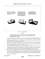
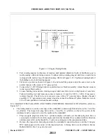
4. Lubricate the gear support shaft with clean lubricating oil and install the drive gear assembly so
the slots of the coupling bushings will be in the approximate position for aligning with the drive
coupling lugs on the magneto.
5. Insert the retainer into the gear hub slot. Apply a film of Lubriplate grease to each of the new
rubber bushings and insert the bushings into the retainers, rounded long edges first.
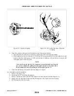
6. Place a new gasket on the magneto flange. Install the magneto carefully so the drive coupling lugs
mate with the slots of the drive bushings. Install and snug down the two sets of attaching screws.
Do not tighten at this time.
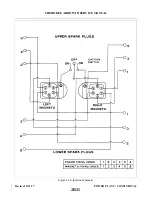
7. Breaker point opening may be checked by use of a suitable timing light. Tap the magneto case
with a non-marring hammer, counterclockwise (from the rear) to make certain the points are
closed. After the timing light indicates that the points are closed, tap the magneto lightly clockwise
until the points are open. Tighten the magneto attaching nuts.
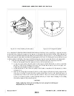
8. Check timing by backing up crankshaft approximately 5 degrees and tapping gently forward until
the timing light indicates opening of breaker points. If timing is correct, the 20 degree mark
(midway between the 16 and 24 stamped on the crankshaft) will appear in the center of the
inspection hole. The crankshaft has punch marks in 2 degree increments with 16 and 24 at each
end. Tighten the magneto attachment nuts and replace the plug in the inspection hole on top of the
engine.
8-40. HARNESS ASSEMBLY.
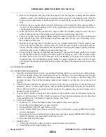
8-41. INSPECTION OF HARNESS.
a.
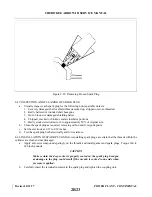
Check the lead assemblies for nicks, cuts, mutilated braiding, badly worn section or any other evidence
of physical damage. Inspect the spark plug sleeves for chafing or tears and damaged or stripped
threads on coupling nuts. Check the compression spring to see if it is broken or distorted. Inspect the
grommet for tears. Check all the mounting brackets and clamps to see that they are secure and not
cracked.
b. Should a harness problem be suspected, integrity of the harness wiring may be checked using an
ohmmeter, buzzer, or other suitable device such as the Bendix/ECD High Tension Lead Tester Kits,
P/N 11-8950 or 11-8950-1; check each lead for continuity. If continuity does not exist, harness wire is
broken and must be replaced.
c.
If an insulation failure is suspected, the condition of the insulation may be determined using the
Bendix 11-8950 and the 11-8950-1 High Tension Lead Tester Kits manufactured by the Electrical
Components Division, The Bendix Corporation, Sidney, New York.
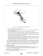
d. Test Unit Preparation:
1. Install two “C” cells in the battery holder in accordance with correct position.
2. Check that red and black leads are open-circuited.
3. Depress PRESS-TO-TEST push-button switch.
4. Insure INDICATOR lamp flashes and GAP fires intermittently as long as PRESS-TO - T E S T
switch is depressed.
5. Interconnect both red and black high voltage leads and again depress PRESS-TO-TEST switch.
INDICATOR lamp only should flash. GAP does not fire.
6. Disconnect black and red leads.
e.
Insulation Test:
1. Attach clip of red high voltage test lead to ignition harness lead terminal.
2. Attach black test lead clip to lead ferrule.
Revised: 8/31/77
2B14
CHEROKEE ARROW III SERVICE MANUAL
POWER PLANT - CONTINENTAL
Summary of Contents for ARROW III
Page 4: ...THIS PAGE INTENTIONALLY LEFT BLANK 1A4...
Page 12: ...THIS PAGE INTENTIONALLY LEFT BLANK 1A12...
Page 94: ...Figure 4 2 Wing Installation Revised 2 13 89 1D22 CHEROKEE ARROW III SERVICE MANUAL STRUCTURES...
Page 171: ...lH3 INTENTIONALLY LEFT BLANK...
Page 172: ...lH4 INTENTIONALLY LEFT BLANK...
Page 286: ...THIS PAGE INTENTIONALLY LEFT BLANK Revised 2 13 89 2A8...
Page 528: ...INTENTIONALLY LEFT BLANK 2K10 THRU 2L24 2K10...

