141
VSX-49TX, VSX-47TX
7. GENERAL INFORMATION
7.1 DIAGNOSIS
7.1.1 Test Mode
• How to Enter the Test Mode
With the attached Remote Control Unit.
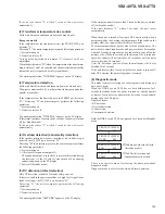
1. Press the [REMOTE SETUP]+[1] keys simultaneously to enter
the "SECRET" mode.
LCD displays the "SECRET [DVD/LD]"
2. Press the [
%
]+[
fi
]+[VCR2] keys simultaneously to enter the Test
Mode.
LCD displays the "SECRET [VCR2]".
1. Test Mode ON (Press [C] key)
• Set the function to CD.
• Set the signal selection to AUTO.
• Set the tuner-preset data.
• Set speaker A to ON and speaker B to OFF.
• Set the BASS and TREBLE to +6.
• Set the remaining items to their factory settings.
Display:
TEST MODE
2. Test Mode OFF (Press [0] key)
When you quit Test mode, the unit automatically enters STANDBY
status.
Note: Do NOT quit Test mode by disconnecting the power cord.
Doing so prevents factory-set data from being written to
EEPROM to backup the data.
3. Items to be checked in Test mode
For checking the main unit of a product: Remote control codes
A55F+A500 ([1] key) through A509 ([0] key).
1. FL display check (Press [1] key)
Normal display
→
All FLs and LEDs on
→
All FLs and LEDs off
→
Normal display
→
. . .
Display transition:
TEST MODE
→
FL ALL ON
→
FL ALL OFF
→
TEST MODE
2. Bass and treble operations (Press [4] key)
Each time this code is issued, the bass and treble values change.
In modes (THX, Direct, Multichannel-Direct) in which tone control
is invalid, the display also changes as shown below.
To use, select a mode (Standard, etc.) in which tone control is valid.
Display transition:
TRE/BASS 0dB
→
TRE/BASS MAX
→
TRE/BASS 0dB
Remarks:
In Test mode, the bass and treble keys on the main unit functions as
follows:
+ : 0 dB
→
+6 dB
→
0 dB
→
+6 dB, . . .
– : 0 dB
→
– 6 dB
→
0 dB
→
– 6 dB, . . .
3. Master volume switching (Press [5] key)
When this code is issued, the master volume changes.
Trimming of all channels becomes 0 dB at this time.
Display transition:
TEST VOL MIN
→
TEST VOL MAX
→
TEST VOL MIN
4. Tuner 9K/10K switching (Press [6] key)
When this code is issued, the reception frequency interval of the
tuner cyclically changes.
The code is valid only with models (SD models) having 9K/10K
switching capability.
Display transition:
TEST TUN 9K
→
TEST TUN 10K
→
TEST TUN 9K
5. FAN ON/OFF (Press [8] key)
When this code is issued, the fan turns on or off.
The code is valid only with models having a fan.
Display transition:
FAN OFF
→
FAN ON
OFF : Fan stops.
ON
: Fan operates.
6. Microphone input check (Press [9] key)
When this code is issued, Direct mode is selected (a path that
bypasses DSP), and a microphone input signal will be output from
the pre-output on the front panel.
• Set the function to CD.
• Set the signal selection to AUTO.
Display transition:
TEST MIC CHECK
7. RS232C operation check (Press [2] key)
When this code is issued, the RS-232C transmission port is switched
to act as a general-purpose port, and self-check of data input/output
ports is performed.
The signal ("L" output) at the data output port is read to the data-
input port and checked as to whether it is correct or not. "H" is
output from the CTS port.
If the port self-check successfully ends:
Display:
MAIN RS232C OK
If the port self-check fails:
Display:
MAIN RS232C NG
8. Tuner: Auto scan (Press [3] key)
When this code is issued, an auto scan operation begins.
The step of frequency increment is forcibly set to 9K.
If the function is not Tuner, it is switched to Tuner, then auto scanning
starts from 88.5 MHz FM in the + direction.
When the code is issued again, auto scan starts from 1062 kHz AM
in the – direction.
Summary of Contents for VSA-AX10
Page 123: ...VSX 49TX VSX 47TX 93 A B C D 1 2 3 4 1 2 3 4 L SIDE B ANALOG IN A D ASSY L ANP7390 A IC3901 ...
Page 129: ...VSX 49TX VSX 47TX 99 A B C D 1 2 3 4 1 2 3 4 Q SIDE B VR PRE OUT ASSY Q ANP7392 A ...
Page 132: ...VSX 49TX VSX 47TX 102 A B C D 1 2 3 4 1 2 3 4 R Q5814 Q5813 Q5805 IC5806 IC5807 ...
Page 195: ...VSX 49TX VSX 47TX 165 A B C D 1 2 3 4 1 2 3 4 SIDE B K1 K2 K12 K13 K18 K6 K7 EL HON GND VDD ...
Page 197: ...VSX 49TX VSX 47TX 167 A B C D 1 2 3 4 1 2 3 4 SIDE A SIDE B 7 3 2 2 PCB DIAGRAM ...


