background image

32


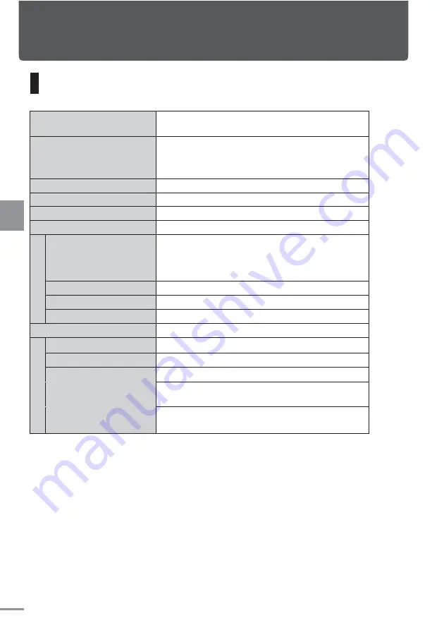
Main specifications


Product name 

Model No: TVM-PW910T 

9-Inch Wide VGA Private Monitor 

Device dimension (including 
protrusion) 

239.5mm (W) × 143.0mm (H) × 

127.0mm (D)


(when the monitor is at 90°) 

Weight  

About 900 g 

Power/maximum current  

DC14.4V/1A


Grounding 

Minus-earth system 

Temperature range 

 10℃

~+

 60℃


L

E


p

an
el


Screen size 

9V-Type Wide VGA 

Effective area

Horizontal

 198.0mm ×


Vertical

 112.1mm


Display 

Transmission type TN LED 

Drive  

TFT Active Matrix Method 

Resolution 

Horizontal

 800 ×

 Vertical

 480


Light source 

LED


I/O 
ter
m

in

al


Video input terminal 

1 (NTSC) 

Video output terminal 

1 (NTSC) 

HDMI input terminal 

1

 (60Hz 480i/480p/1080i/720p)


Head phone output 
terminal 

1

 (HDMI dedicated)


Power supply terminal 
(USB type) 

1

 (DC5V/1A)


• Specifications per monitor 
• Due to constant improvement, the specifications and appearance may change   
   without prior notice  


Reference


Reference


Summary of Contents for TVM-PW910T

Page 1: ...esponsible To all dealers After connection and installation please pass this booklet to the customer The contents stated in this manual may change without notice Duplicating this manual without permission is strictly prohibited When using the product always read the Safety Precautions Not observing the precautions on safety may endanger the user or others or cause property damage This manual conta...

Page 2: ...ghtness 13 Turning the illumination ON OFF 13 Settings Menu 14 How to operate and set the menu 14 Screen setting 15 Sound setting 16 Brightness setting 17 Illumination setting 18 Operation setting 18 Brightness setting 19 Source setting 20 Misc settings 21 HDMI Link setting 21 Logo setting 22 Initialize setting reset 23 How to connect Before connecting what you should know 24 Power and AV interfac...

Page 3: ... not install or wire in an area that obstructs airbag action When installed in vehicles with airbags check the precautions of the car manufacturer regarding the work to avoid airbag malfunction and cause fatal accident Warning Prohibited Do not install at locations that obstruct front view or driving or locations that pose danger to passenger May cause traffic accident or injury Do not open the co...

Page 4: ...ate with tape if the cord has no cover Short circuit may cause fire electric shock or damage Wire in such a way that the cord is not squeezed inside the movable part the car body bolt sheet rail Broken wire or short circuit may cause fire electric shock or damage Mandatory Secure the cord so that it does not obstruct driving If it is caught by the steering wheel selection bar or hand brake acciden...

Page 5: ...accident or electric shock Mandatory When using it always fasten seat belt Not fastening the seat belt may cause serious accident during emergency brake Warning Prohibited The cord should not come in contact with the high temperature parts of the car body May cause fire or electric shock Do not connect the electrical lead wire to the battery directly May cause fire or electric shock Do not branch ...

Page 6: ... of electric shock from lightning Do not disassemble or modify May cause traffic accident fire or electric shock Man dator Whenreplacing the fuse always use thecapacity specified ampere Using fuse outside the capacity required may cause fire or damage Warning Mandatory In case of breakdown stop using immediately and always consult the dealer for service Using under such situation may cause unexpec...

Page 7: ...to high temperature the LED screen can be damaged if used under direct sunlight for extended period Thus if possible avoid using under direct sunlight Use the device within the temperature range recommended Do not press the LED screen too hard to avoid breaking or damaging it Do not touch the LED screen unnecessarily to avoid crack or dirt Small dark dots or bright shining dots may be seen on the ...

Page 8: ...ace cable fuse is 3A Preparation 取り付けや配線は専門業者にご依頼ください 取り付けや配線は 専門技術と経験が必要です お買い 上げの販売店にご相談ください Request for experienced technician to perform the installation and wiring Installation and wiring require technicians with experience please consult your dealer To preventelectrical shortcircuitduring installation turnOFFthe car power andremove the negative terminal of the battery After all installation ...

Page 9: ...Turn OFF the power LED screen External light sensor The sensor that auto adjusts the brightness of the screen to suit the surroundings and turns the illumination ON OFF Page 13 Head phone terminal 3 5mm can be connected to stereo mini plug head phone HDMI input terminal s voice output Power supply terminal DC5V 1A USB type Supplies power to smart phone HDMI input terminal Page 26 Illumination Blue...

Page 10: ...as previsouly turned OFF manually When turning ON the power press the SRC PWR button When turning OFF the power While the power is ON press the SRC PWR button and hold Operation Preparation Always turn on the car engine to prevent wearing off the battery Precaution s 2 ...

Page 11: ...c by connecting the head phone to the head phone terminal Page 9 on the side of the body Press VOL ー button VOL ー To lower the volume VOL To increase the volume The volume can be adjusted from 0 min to 30 max 0 means mute If the device is not connected or there is no picture signal from the input the current input will not be displayed on the upper left Can be changed to suit the device connected ...

Page 12: ... full screen The ratio at the centre of the image will become smaller while the right and left sides will become larger CINEMA Will enlarge the image to the top and bottom and will display the picture on full screen The top bottom of the image will be cut ZOOM Will enlarge the image to the top and bottom as well as right and left uniformly The edges a part of the top bottom and right left of the i...

Page 13: ...utomatically Day time The optimum mode for the surrounding brightness during daytime Evening The optimum mode for the surrounding light darkness in the evening Night The optimum mode for the surrounding darkness at night Changing the default setting brightness of each mode The default setting brightness of each mode Day time Evening and Night time can be changed To adjust the setting go to Brightn...

Page 14: ...ginal screen If no operation is done on the screen and the menu screen is left without entry for about 30 seconds the display will be off After setting the items the user can reset to return to the default setting factory setting Page 23 Settings Settings Menu item Set item Set value PICTURE Page 15 MODE DYNAMIC STANDARD CINEMA USER BRIGHTNESS 24 24 CONTRAST 24 24 COLOR 24 24 HUE 24 24 SHARPNESS 7...

Page 15: ...d to the image description DYNAMIC Emphasizes on the contrast to create a bright image STANDARD Standard setting CINEMA Controls the contrast to darken the image and make it easier to view USER Adjusts to the quality desired by the user The following can be set only under USER mode for adjusting to the quality desired Brightness To adjust screen brightness Set value 24 24 Contrast To adjust the co...

Page 16: ...e at the right of the screen Adjust using the VOL button When adjustment is complete press the W MENU button Move the cursor to the menu item on the left of the screen Select Exit with VOL button then press the W MENU button The menu screen will exit Set value 3 3 Set value 3 3 Treble Set the intensity under treble Bass Set the intensity under bass Menu screen exit SOUND Treble Bass Exit 0 0 Exit ...

Page 17: ...ton Move the cursor to the current set value on the right of the screen Adjust using the VOL button Once the adjustment is complete press the W MENU button Move the cursor to the menu item on the left of the screen Select Exit using the VOL button then press W MENU button The menu screen will exit Set value 1 dark 32 bright 夜 Adjust the value in each mode Exit Menu screen exit Settings BRIGHTNESS ...

Page 18: ...ll appear Select the ILLUMINATION using the VOL button then press the W MENU button ILLUMINATION menu will appear Select Operation with VOL button then press W MENU button Move the cursor to the current set value on the right of the screen Select Key or Dimmer using the VOL button Press and hold to switch between Key and Dimmer Once the setting is complete press the W MENU button Move the cursor t...

Page 19: ...LUMINATION menu will appear Select Brightness using the VOL button then press W MENU button Move the cursor to the current set value on the right of the screen Select either 1 2 or 3 using the VOL button Press and hold to switch between the set values Once setting is complete press W MENU button Move the cursor to the menu item on the left of the screen Select Exit using the VOL button then press ...

Page 20: ...ppear Select SOURCE using the VOL button then press the W MENU button The SOURCE Menu will appear Select the source VIDEO or HDMI desired with the VOL button then press the W MENU button Move the cursor to the current set value on the right of the screen Change with VOL button Select Exit using the VOL button then press the W MENU button The menu screen will exit SOURCE VIDEO HDMI Exit VIDEO HDMI ...

Page 21: ...e left of the screen Select Exit using the VOL button then press the W MENU button The menu screen will exit The device complies with HDMI CEC Consumer Electronics Control standard so linked operation between devices is possible However despite compliance with the standard each manufacturer may have its own unique expansion function or inter changeability and some or all of the functions may not b...

Page 22: ...tton MISC menu will appear Select Logo using the VOL button then press the W MENU button Move the cursor to the current set value on the right of the screen Select OFF or ON using the VOL button Press and hold to switch between ON OFF Once the setting is complete press the W MENU button Move the cursor to the menu item on the left of the screen Select Exit using the VOL button then press the W MEN...

Page 23: ...e SRC PWR while continuing to press the W MENU button The power of the monitor will turn ON and the system menu screen will appear Make sure that the RESET button is selected then press W MENU button Upon pressing the settings will be reset and the device will restart automatically Operate the settings as required SYSTEM RESET VERSION 8C05 FO Settings 1 2 ...

Page 24: ...ld be from the accessories power source ACC power Taking the power from the battery may cause the battery to be flat Accessories power will be cut off when the engine key is pulled out When the connector beside the monitor is connected make sure that the direction is correct and insert until a catch sound is heard Do not force in to avoid breakdown or damage When removing the connector pull out to...

Page 25: ...wer and AV interface cable accessories Black Red Fuse resistance 3A EARTH ACC Connect firmly to the metal of the car body When the car engine switch is the location of the ACC connect this to the power circuit provided Yellow VIDEO OUTPUT Yellow Connect to the second set of picture input terminal 3m 1 5m 1 5m Connect to the picture output terminal of the connector such as DVD Player or terrestrial...

Page 26: ... HDMI Licensing LLC HDMI terminal The picture sound and control signal can be transmitted digitally with a single cable and clear picture can be viewed through DVB Digital Video Broadcast Depending on the device connected normal picture and sound may not be produced In such case use other output terminals The picture of the equipment connected to the device using HDMI cable cannot be output to ano...

Page 27: ...en the shafts then adjust the position of the shaft guide Precautions on installation The device is a boot mounted type It cannot be used in vehicles with no boot and cannot be used in vehicles with bucket seat or head rest In vehicles with special shafts boots or seats it may not be able to install the device If the shaft lock is not working do not install the device The shock to the device will ...

Page 28: ...e Adjust install Shaft guide left Pull to adjust Shaft guide right Slide to the right left of the hole then change the position as required to install Or Shaftguide Hook Or Insert the hook s gap into the protrusion of the fixture then lock the claw properly to install Protrusion Lock the hook properly into the fixture to install How to adjust Slide the right shaft guide to adjust て If the shaft di...

Page 29: ...ight cover as well Cover C bracket Cover ー Installing the monitor continued Remove the cover on the left of the fixture Connect the power and AV interface cable Connect the power and AV interface cable connection of the accessories to its connector terminal The cable is wired along the cable guide Install the fixture to the shaft boot of the headrest Shaft lock button Guide Connector How to connec...

Page 30: ... button is on the right remove the cover on the right and press Adjust the height of the headrest Push the shaft lock button from this gap using the fingers Put back the cover Install the monitor cover Cover For safety reasons the monitor cover should always be installed How to connect Precautions Monitor cover accessory 6 7 8 ...

Page 31: ...the following procedure Check the connection and installation again Check the connection and installation ensure that they are not loosened or removed Start the car engine Reset the device Refer to the Setting initialization Reset Page 23 on how to reset Check the operation of the device Adjust the screen to the desired angle How to connect 1 3 4 5 2 ...

Page 32: ...de VGA Effective area Horizontal 198 0mm Vertical 112 1mm Display Transmission type TN LED Drive TFT Active Matrix Method Resolution Horizontal 800 Vertical 480 Light source LED I O terminal Video input terminal 1 NTSC Video output terminal 1 NTSC HDMI input terminal 1 60Hz 480i 480p 1080i 720p Head phone output terminal 1 HDMI dedicated Power supply terminal USB type 1 DC5V 1A Specifications per ...

Page 33: ...5 34 11 No SOUND Is the volume set to minimum 0 When the headphone is connected Is it HDMI input The headphone terminal can only produce the sound of the HDMI input terminal HDMI cannot be used if not connected 11 11 The PICTURE is in landscape or portrait orientation Try to change to wide mode Depending on the wide mode selected the picture can be longer horizontally or vertically 12 The PICTURE ...

Page 34: ...e LED monitor s surrounding temperature is high the screen may become dark Cool down the interior of the car with air con or other means 15 The picture hue is odd The HUE is not properly adjusted 15 There are small black or bright dots on the LED screen This is not breakdown but characteristic of LED screen Overheating detection The device is equipped with temperature sensor if the temperature is ...

Page 35: ...35 Memo ...

Page 36: ...8 8 Honkomagome 2 chome Bunkyo ku Tokyo 113 0021 Japan http pioneer jp group index e html PIONEER ELECTRONICS ASIACENTRE PTE LTD 2 Jalan Kilang Barat 07 01 Singapore 159346 Tel 65 6378 7888 www pioneer com sg U01UG589RZZ 0 ...

Reviews: