


PRA-BD11
12
1
2
3
4
1
2
3
4
C
D
F
A
B
E
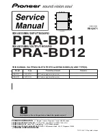
3.2 OVERALL CONNECTION DIAGRAM
÷
When ordering service parts, be sure to refer to "EXPLODED VIEWS and PARTS LIST" or
"PCB PARTS LIST".
÷
The
>
mark found on some component parts indicates the importance of the safety factor
of the part. Therefore, when replacing, be sure to use parts of identical designation.
÷
: The power supply is shown with the marked box.
A
1/4 -
A
4/4
PRV-LX1
AVIB ASSY (DWV1198)
A
B
1/2 -
B
2/2
B
1
2
3
4
OFF
FSK
DINB ASSY
(DWV1200)
PRA-BD11
PRA-BD12
DOOB ASSY
(DWV1201)
To. PCIB ASSY
(CN2104, CN2103)
To. JKIB ASSY
(CN7613)
To. JKIB ASSY (CN7611)
To. JKIB ASSY (CN7402)
To. PWRB ASSY
(CN2)
To. DECB ASSY
(CN1651, CN1811)
To. PCIB ASSY
(CN2101)
S8602 (DIP- SW)
AKN7032
DKN1192
DKN1192
Summary of Contents for PRA-BD11
Page 19: ...PRA BD11 19 5 6 7 8 5 6 7 8 C D F A B E A 3 4 ...
Page 21: ...PRA BD11 21 5 6 7 8 5 6 7 8 C D F A B E ...
Page 23: ...PRA BD11 23 5 6 7 8 5 6 7 8 C D F A B E B 1 2 2 2 B 2 2 B 2 2 B 2 2 B 2 2 B 2 2 B 2 2 B 2 2 B ...
Page 25: ...PRA BD11 25 5 6 7 8 5 6 7 8 C D F A B E B 2 2 1 2 B 1 2 B 1 2 B 1 2 B ...