PDP-LX5080D
77
5
6
7
8
5
6
7
8
C
D
F
A
B
E
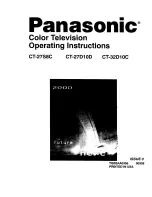
5.6.2 SPECIFICATION OF THE FAN CONTROL
The internal fan cools down the MTB and Power blocks.
The external fans cool down the whole unit.
• The operating temperature of the fan is higher than the ambient temperature, because the sensor temperature is read by
the microcomputer.
• If the critical values for signals are displayed in the address circuit, the fan may be activated or be rotated at higher speed
in response to values lower than the set temperature values shown above.
•
W
hen the temperature rises, the sensor voltage of TEMP2 decreases.
•
W
hen the voltage of the DAC output for external FA
N
decreases, rotation speed of FA
N
rises.
DIGITAL Assy
TANSHI Assy
If an emergency signal
is detected, it will be
transmitted.
DAC output
Block diagram
Operation specifications
Notes:
FAN_VCC1
0 to 12
V
0 to 12
V
FAN_VCC2
TEMP2
FAN_NG1
FAN_ON1
FAN_CONT1
FAN_NG2
FAN_ON2
FAN_CONT2
HIGH
LO
W
Temperature SD
STOP
37.0 ºC
40.0 ºC
42.0 ºC
45.0 ºC
62.0 ºC
DAC2
DAC1
STOP
0xFF
36.5 ºC
3
8
.5 ºC
46.0 ºC
60.0 ºC
62.0 ºC
Internal FA
N
External FA
N
FA
N
_1_
REG
OR
FA
N
_2_
REG
TEMP2
IF_Ucom
Main_Ucom
Module_Ucom
R
R
Internal fan
External fans
FHD FAN
CONNECT
Assy
MAIN Assy
The Main micro-
computer controls
the IF microcomputer
as a port expander.
Detection of
disconnection
Detection of
disconnection
V
OLTAGE
CO
N
TROL
V
OLTAGE
CO
N
TROL
Summary of Contents for KURO PDP-LX508D
Page 19: ...PDP LX5080D 19 5 6 7 8 5 6 7 8 C D F A B E ...
Page 20: ...PDP LX5080D 20 1 2 3 4 1 2 3 4 C D F A B E 4 BLOCK DIAGRAM 4 1 OVERALL WIRING DIAGRAM 1 2 ...
Page 22: ...PDP LX5080D 22 1 2 3 4 1 2 3 4 C D F A B E 4 2 OVERALL WIRING DIAGRAM 2 2 ...
Page 23: ...PDP LX5080D 23 5 6 7 8 5 6 7 8 C D F A B E ...
Page 159: ...PDP LX5080D 159 5 6 7 8 5 6 7 8 C D F A B E ...
Page 170: ...PDP LX5080D 170 1 2 3 4 1 2 3 4 C D F A B E 10 6 PANEL CHASSIS SECTION ...