


21
CX-890
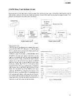
4. DISASSEMBLY
-
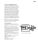
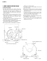
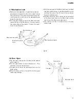
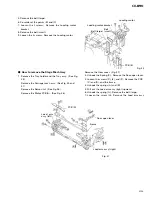
How to remove the Tray Assy
1. Apply about 6V current to the Cam gear motor until
all holes match at the position (A) (elevation OK posi-
tion).
2. Hook the three springs B temporarily as shown in Fig.
28. While pushing the Tray holder lock arms (right
and left) in the direction (C), remove the Tray holder.
3. Lift up the Tray assy to remove it.
* Be careful not to remove the Tray hooks from the Tray
assy.
-
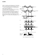
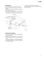
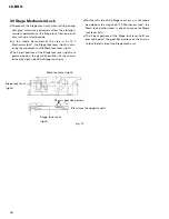
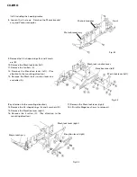
How to remove the Carriage Mech Assy
1. Insert a short pin into the flexible PCB of the Pickup
unit.
2. While opening the resin hooks, remove the cover
from the Servo unit.
3. Disconnect the flexible PCBs from the connectors
CN101 and CN301.
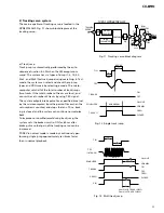
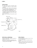
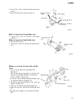
4. Remove the Tray holder and the Tray assy. (See
above)
5. Rotate the Cam gear motor until the positions of all
holes (E) match, then stop the motor.
(The Carriage Mech assy will stop as shown in the
Fig.30.)
* When the positions of all holes match, they will be
completely covered by the Carriage mech assy.
* To rotate the Cam Gear motor, see "How to remove
the Tray assy".
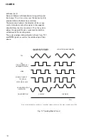
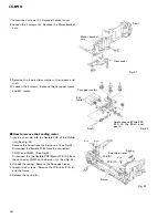
6. Unhook the spring A.
7. Remove the flexible holder B (while opening the
hooks).
8. Remove the flexible PCB (C) from the motor. (The
flexible PCB (C) has been stuck on the motor with
double-sided adhesive tape.)
9. Loosen the fixing screw and remove the flexible
holder.
ELV motor
Cam gear motor
Approximately DC 6V
Tray holder
Tray holder lock arm
Tray holder
lock arm
Tray
hooks
Tray Assy
Cover
CN101
CN301
Match the hole positions
Flexible
holder
Fig.28
Fig. 29
Fig. 30
Short pin
Tray
hooks
Summary of Contents for CDX-MG6056ZH
Page 5: ...4 CDX MG6346ZH MG6446ZH 2 2 EXTERIOR ...
Page 7: ...6 CDX MG6346ZH MG6446ZH 2 3 CD MECHANISM ...
Page 14: ...13 CDX MG6346ZH MG6446ZH 5 6 7 8 5 6 7 8 D C B A A A b A EXTENSION UNIT ...
Page 15: ...14 CDX MG6346ZH MG6446ZH 1 2 3 4 1 2 3 4 D C B A 1 A a A b D CD CORE UNIT STS UNIT A a ...
Page 16: ...15 CDX MG6346ZH MG6446ZH 5 6 7 8 5 6 7 8 D C B A A a A b B 2 B KEYBOARD UNIT A a ...
Page 17: ...16 CDX MG6346ZH MG6446ZH 1 2 3 4 1 2 3 4 D C B A A a A b 1 A EXTENSION UNIT A b ...
Page 18: ...17 CDX MG6346ZH MG6446ZH 5 6 7 8 5 6 7 8 D C B A A a A b 2 A b ...
Page 28: ...27 CDX MG6346ZH MG6446ZH 1 2 3 4 1 2 3 4 D C B A CN701 CN901 EXTENSION UNIT SIDE B A A B D ...
Page 30: ...29 CDX MG6346ZH MG6446ZH 1 2 3 4 1 2 3 4 D C B A SIDE B KEYBOARD UNIT B B ...
Page 32: ...31 CDX MG6346ZH MG6446ZH 1 2 3 4 1 2 3 4 D C B A CD CORE UNIT SERVO UNIT SIDE B C C ...
Page 34: ...33 CDX MG6346ZH MG6446ZH 1 2 3 4 1 2 3 4 D C B A CD CORE UNIT STS UNIT SIDE B D D ...
Page 36: ...M M4 CARRIAGE 1 12 D CN301 35 CDX MG6346ZH MG6446ZH 5 6 7 8 5 6 7 8 D C B A E C ...
Page 38: ...1 41 G CN801 37 CDX MG6346ZH MG6446ZH 1 2 3 4 1 2 3 4 D C B A MOTOR PCB A F SIDE B F D ...


