background image

Home Automation Kit 


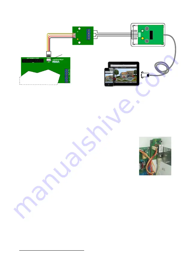
Figure 1.


Direct connection diagram

2


6.


Connect the LCL-11A’s serial cable to the home automation system. Connection can be made 
either directly with the 9 pin connector, or via the Serial-to-UBS adaptor. The adaptor’s driver 

are on the CD, that’s in its package. 

Network (LAN) connection 

To connect the alarm system to the home automation system via network, you will need Pima’s 
net4pro-i card. The card is supplied mounted on a bracket. 
To connect via network, follow the next steps: 

1.


Mount the net4pro-i in the control panel 

enclosure: 

a.


Release the top-right screw of the 

control panel’s circuit. 

b.


Push the net4pro-i bracket’s grip 

against the right side of the 

enclosure and mount it. 

c.


Fasten the control panel’s screw 

together with the bracket. 

2.


Connect the Molex cable to the control 

panel’s SERIAL connector. 


3.


Connect the net4pro-i to LAN using CAT-5 cable (not supplied). 

4.


Program the net4pro-i. See next section. 


2

 Home automation image by Jiri Svobi under CC Sharealike license 

LCL-11A

SERIAL


Connector

TX

RX

+V
GND

SA

-232

TX

RX

SA-232

JP

3

Control Panel

4 Wire braid

Home Automation System

Summary of Contents for LCL-11A

Page 1: ...Home Automation Kit For the Hunter Pro and Captain 8 Alarm Systems Installation Guide Pima Electronic Systems Ltd...

Page 2: ...which have been adjusted to these systems The connection to the Home Automation system can be made in one of two ways Directly using the supplied cable SA 232 converter and LCL 11A adaptor ver H Via...

Page 3: ...ether with the bracket d Connect the Molex cable to the control panel s SERIAL connector 2 Open the LCL 11A box by squeezing and removing its cover 3 Remove the RJ 11 jack a Use the supplied keychain...

Page 4: ...connect via network follow the next steps 1 Mount the net4pro i in the control panel enclosure a Release the top right screw of the control panel s circuit b Push the net4pro i bracket s grip against...

Page 5: ...Installation 5 Figure 2 Network connection diagram net4pro i Control Panel Home Automation System LAN...

Page 6: ...nstaller The software will automatically search for XPort devices on the LAN To search manually click the Search button on the menu bar In the next example a device was found in the address 192 168 0...

Page 7: ...ata Baud Rate 2400 Check Enable Packing Idle Gap Time 250 3 Click OK and wait for the message DONE next to the OK button to disappear Connection 1 Under Channel 1 on the purple side bar click Connecti...

Page 8: ...ng from burglary robbery fire or otherwise or that the Product will in all cases provide adequate warning or protection The User understands that a properly installed and maintained equipment may only...

Reviews: