background image

PNOZ X10.1

Operating Manual PNOZ X10.1
20005-EN-10

| 13

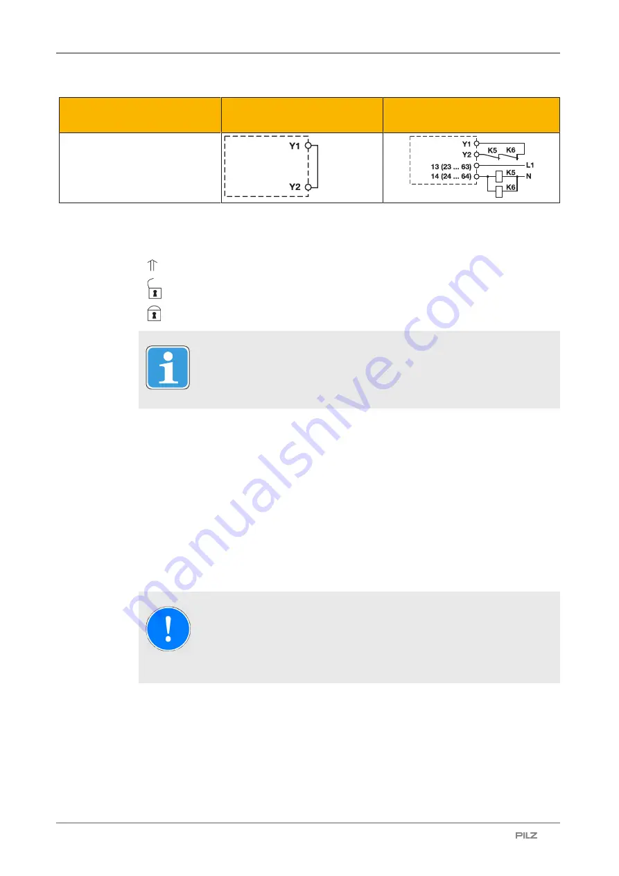
Feedback loop

Without feedback loop monit-
oring

With feedback loop monitoring

Link or contacts from external
contactors

Legend

}

S1/S2: E-STOP/safety gate switch

}

S3: Reset button

}

: Switch operated

}

: Gate open

}

: Gate closed

INFORMATION

With automatic start and manual start, Y1 and S37 must not be linked.

Operation

When the relay outputs are switched on, the mechanical contact on the relay cannot be
tested automatically. Depending on the operational environment, measures to detect the
non-opening of switching elements may be required under some circumstances.

When the product is used in accordance with the European Machinery Directive, a check
must be carried out to ensure that the safety contacts on the relay outputs open correctly.
Open the safety contacts (switch off output) and start the device again, so that the internal
diagnostics can check that the safety contacts open correctly

}

for SIL CL 3/PL e at least 1x per month

}

for SIL CL 2/PL d at least 1x per year

NOTICE

The safety function should be checked after initial commissioning and each
time the plant/machine is changed. The safety functions may only be
checked by qualified personnel.

Summary of Contents for 774746

Page 1: ...PNOZ X10 1 Operating Manual 20005 EN 10 Safety relays...

Page 2: ...nta tion will be gratefully received Source code from third party manufacturers or open source software has been used for some components The relevant licence information is available on the Internet...

Page 3: ...y 6 Disposal 6 For your safety 6 Unit features 7 Safety features 7 Block diagram terminal configuration 7 Types AC 7 Type DC 8 Function Description 8 Operating modes 8 Timing diagram 9 Installation 9...

Page 4: ...larly important is identified as follows DANGER This warning must be heeded It warns of a hazardous situation that poses an immediate threat of serious injury and death and indicates preventive measur...

Page 5: ...details see Technical details 15 NOTICE EMC compliant electrical installation The product is designed for use in an industrial environment The product may cause interference if installed in other envi...

Page 6: ...wledge of the generic and specialist standards applicable to the specific application Warranty and liability All claims to warranty and liability will be rendered invalid if The product was used contr...

Page 7: ...relay See order reference for unit types Safety features The safety relay meets the following safety requirements The circuit is redundant with built in self monitoring The safety function remains ef...

Page 8: ...osition Safety contacts 13 14 23 24 33 34 43 44 53 54 and 63 64 are closed auxiliary contacts 71 72 81 82 91 92 and 01 02 are opened The unit is active Input circuit is opened e g E STOP pushbutton op...

Page 9: ...osed and goes out when the start circuit is opened Increase in the number of available contacts by connecting contact expandsion modules or external contactors relays Timing diagram 1 2 3 Legend Power...

Page 10: ...rans mission or the shielding of cables for example Do not switch low currents using contacts that have been used previously with high cur rents Adequate protection must be provided on all output cont...

Page 11: ...h detection of shorts across contacts S1 S22 S21 S12 S11 Y3 S11 Safety gate without detection of shorts across contacts S1 Y3 S12 S12 S21 S11 S22 S1 S2 S22 S21 S11 S12 Y3 Safety gate with detection of...

Page 12: ...rts across contacts Dual channel with detection of shorts across contacts Automatic start Y1 S37 Y1 S37 Automatic start with start up test Y1 S37 S33 S34 Simultaneity S1 and S2 150 ms Manual start Y1...

Page 13: ...ironment measures to detect the non opening of switching elements may be required under some circumstances When the product is used in accordance with the European Machinery Directive a check must be...

Page 14: ...s in the operating position K3 Start button is closed Faults Interference Earth fault The supply voltage fails and the safety contacts open Once the cause of the respective fault has been rectified an...

Page 15: ...24 V 24 V Feedback loop DC 24 V 24 V Current at Input circuit DC 50 mA 50 mA Start circuit DC 100 mA 100 mA Feedback loop DC 100 mA 100 mA Min input resistance at power on 89 Ohm 89 Ohm Max overall c...

Page 16: ...A 0 01 A Max current 8 A 8 A Max power 200 W 200 W Utilisation category of auxiliary con tacts AC1 at 240 V 240 V Min current 0 01 A 0 01 A Max current 8 A 8 A Max power 2000 VA 2000 VA DC1 at 24 V 2...

Page 17: ...10 A Circuit breaker 24V AC DC characteristic B C 6 A 6 A External contact fuse protection auxiliary contacts Max melting integral 240 A s 240 A s Blow out fuse quick 10 A 10 A Blow out fuse slow 6 A...

Page 18: ...00 ms With automatic start after power on max 320 ms 300 ms With manual start typ 200 ms 200 ms With manual start max 250 ms 250 ms With monitored start typ 150 ms 165 ms With monitored start max 200...

Page 19: ...Mounting area e g control cab inet IP54 IP54 Mechanical data 774746 774749 Mounting position Any Any Mechanical life 10 000 000 cycles 10 000 000 cycles Material Bottom PPO UL 94 V0 PPO UL 94 V0 Fron...

Page 20: ...natory notes for the safety related characteristic data The SIL CL value in accordance with EN 62061 corresponds to the SIL value in accord ance with EN 61508 TM is the maximum mission time in accorda...

Page 21: ...ilure rates of the other components Service life graph The service life graphs indicate the number of cycles from which failures due to wear must be expected The wear is mainly caused by the electrica...

Page 22: ...ew terminals 774749 EC declaration of conformity This product these products meet the requirements of the directive 2006 42 EC for ma chinery of the European Parliament and of the Council The complete...

Page 23: ...g energy efficient products and environmentally friendly solutions We are represented internationally Please refer to our homepage www pilz com for further details or contact our headquarters Headquar...

Reviews: