


PNOZ e1.1p
Operating Manual PNOZ e1.1p
21238-EN-06
12
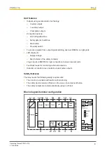
Preparing for operation
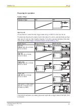
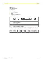
Supply voltage
Supply voltage
AC
DC
A1
F1
A2
L+
L-
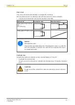
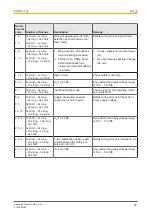
Input circuit
Connect the N/C contact from the trigger element (e.g. E-STOP) to the input circuit.
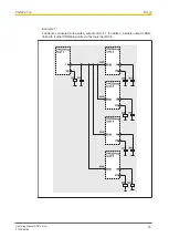
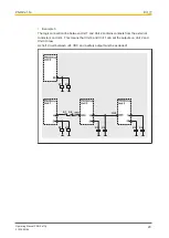
The table describes how the input circuit is wired when the unit is used individually (without
logic input). If units are linked together logically, Y4 must be wired as described in the table
Logic connection between several units [
".
Input circuit
Single-channel
Dual-channel
E-STOP
without
detection of shorts
across contacts
E-STOP
with
detection of shorts
across contacts
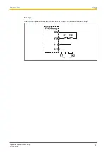
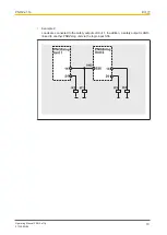
Safety gate
without
detection of shorts
across contacts
Y4
S11
A1
S12
S22
Y4
S11
S12
S22
A1
Safety gate
with
detection of shorts
across contacts
S11
S12
S21
S22
Y4
S21
S21
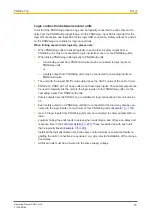
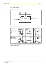
Light guard or safety switch,
detection of shorts across
contacts via ESPE
A1
A2
S12
S22
24 V DC
GND
Y4
S11
The E-STOP pushbutton and safety gate switch symbolise a trigger element with N/C / N/C
combination.


