background image

PSEN ma2.1p-11/-31

Operating Manual PSEN ma2.1p-11/-31
22191-EN-02

19

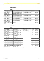
PSS67 Cable M8sf M12sm Female connector, M8

straight, 4-pin

Male connector M12
straight

3 m

380 200

5 m

380 201

10 m

380 202

30 m

380 203

PSS67 Cable M8af M12sm Female connector M8

angled, 4-pin

3 m

380 204

5 m

380 205

10 m

380 206

30 m

380 207

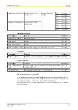
Installation materials

Product type

Features

Order no.

PSEN Winkel / bracket

Mounting bracket

532 110

PSEN spacer

Spacer

534 310

PSEN reverse spacer

Spacer

534 320

PSEN screw M4x16 10pcs

Screws made of high-grade steel with one-way slot

540 310

Connector

Product type

Features

Order no.

PSEN ma adapter

Adapter for connecting the safety switch to PSS67 and PDP67

380 300

Series connection

Product type

Features

Order no.

PSEN i1 Interface for 4
PSEN 2

Interface PSEN i1 for connecting and evaluating several safety
switches PSEN ma

535 110

PDP67 F 8DI ION

Decentralised input module IP67 for PNOZmulti

773 600

EC declaration of conformity

This product/these products meet the requirements of the directive 2006/42/EC for ma-
chinery of the European Parliament and of the Council. The complete EC Declaration of
Conformity is available on the Internet at www.pilz.com/downloads.
Representative: Norbert Fröhlich, Pilz GmbH & Co. KG, Felix-Wankel-Str. 2, 73760 Ost-
fildern, Germany

Summary of Contents for 506401

Page 1: ...PSEN ma2 1p 11 31 Operating Manual 22191 EN 02 PSEN sensor technology...

Page 2: ...umentation will be gratefully received Source code from third party manufacturers or open source software has been used for some components The relevant licence information is available on the Interne...

Page 3: ...el 6 Warranty and liability 6 Disposal 6 For your safety 7 Unit features 7 Function description 7 Block diagram 8 Operating distances 8 Lateral and vertical offset 9 Wiring 10 Pin assignment 10 Requir...

Page 4: ...is particularly important is identified as follows DANGER This warning must be heeded It warns of a hazardous situation that poses an immediate threat of serious injury and death and indicates preven...

Page 5: ...2 1 10 and a suitable evaluation device see Requirements and connection to evaluation devices 10 In series connections the safety switch must only be operated with the following compon ents Actuator P...

Page 6: ...ork equipment devices systems plant and machinery in accordance with the general standards and guidelines for safety technology It is the company s responsibility only to employ personnel who Are fami...

Page 7: ...the unit This will prevent potential contamination Unit features The actuator PSEN 2 1 10 belongs to the safety switch Coded actuator Safety switch with 4 pin M8 male connector 2 safety contacts reed...

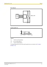
Page 8: ...ctuator Safety switch Magnet 1 2 3 4 Operating distances Sao So Sr Sar mm Somin On Off Legend Sao Assured operating distance Somin Min operating distance Sar Assured release distance The offset indepe...

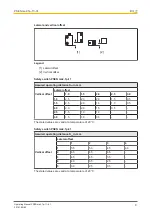
Page 9: ...t Lateral offset 1 0 1 5 2 0 2 5 3 0 1 0 2 5 2 0 2 0 1 5 0 5 1 5 2 5 2 0 1 5 1 0 0 5 2 0 2 0 2 0 1 5 0 5 2 5 1 5 1 0 1 0 3 0 1 5 1 0 0 5 The stated values are valid at a temperature of 20 C Safety swi...

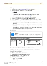
Page 10: ...tion devices with AC supply voltage Overall cable resistance 25 Ohms per channel For details of how to perform the test for shorts across the contacts please refer to the operating manual for the rele...

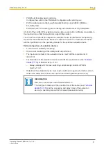
Page 11: ...e operating manual for the selected evaluation device Defined properties of evaluation devices 2 channel with feasibility monitoring Open circuit monitoring of the safety switch is performed The input...

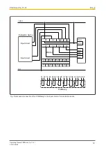
Page 12: ...23 24 21 22 31 33 34 32 41 43 44 42 1 2 3 4 11 12 14 13 1 2 3 4 21 22 24 23 1 2 3 4 31 33 34 32 1 2 3 4 41 43 44 42 24 V I0 0 I0 1 I0 2 I0 3 24 V 0 V PSEN i1 PLC PSENmag Evaluation device Input circui...

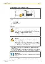
Page 13: ...ance CAUTION Possible loss of the safety function by changing the release distance Sar with non flush installation Installing the safety switch non flush within electrically or magnetically con ductiv...

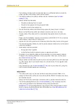
Page 14: ...y switch and actuator facing each other in parallel so that the faces with the product names are opposite each other If possible do not install the safety switch and actuator on to ferromagnetic mater...

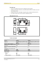
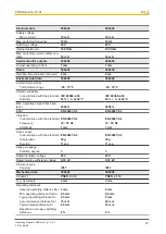
Page 15: ...fety function may only be checked by qualified personnel Dimensions in mm 13 6 5 13 8 5 36 22 6 8 4 5 26 10 6 M8x1 8 5 4 5 36 22 26 Technical details General 506406 506408 Approvals CE EAC Eurasian T...

Page 16: ...C Max operating height above sea level 2000 m 2000 m EMC EN 60947 5 3 EN 60947 5 3 Vibration In accordance with the standard EN 60947 5 2 EN 60947 5 2 Frequency 10 55 Hz 10 55 Hz Amplitude 1 mm 1 mm S...

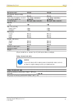
Page 17: ...or 1 1 Nm 1 Nm Dimensions Height 45 mm 45 mm Width 26 mm 26 mm Depth 13 mm 13 mm Actuator dimensions Height 36 mm 36 mm Width 26 mm 26 mm Depth 13 mm 13 mm Weight of safety switch 20 g 20 g Weight of...

Page 18: ...1 actu ator Actuator 512 110 Accessories Cable Product type Connection 1 Connection 2 Length Order no PSEN Kabel Winkel cable angleplug 2m Female connector M8 angled 4 pin Open cable end 2 m 533 110...

Page 19: ...ay slot 540 310 Connector Product type Features Order no PSEN ma adapter Adapter for connecting the safety switch to PSS67 and PDP67 380 300 Series connection Product type Features Order no PSEN i1 In...

Page 20: ...T p the spirit of safety are registered and protected trademarks of Pilz GmbH Co KG in some countries We would point out that product features may vary from the details stated in this document dependi...

Reviews: