


3 Product Description
12
Version: 1.2.1
MS249E
C-863.12 Mercury Controller
value of 12. The PWM signal then has a duty cycle of maximum 50 %, i.e., the output voltage is
maximum 12 V.
INFORMATION
If the positioner is equipped with a PWM amplifier that is supplied via a separate power
adapter:
➢
To achieve the optimum motor performance, use a power adapter for the C-863.12 that
supplies the same output voltage as the power adapter for the PWM amplifier.
The C-863.12 is configured for the maximum operating voltage of the motor with the following
parameters:
Parameter
Description and Possible Values
Maximum Motor
Output (V)
0x7C
Maximum permissible operating voltage of the motor
0 to 48 V
Maximum Motor
Output
0x9
Maximum permissible absolute measure of the control value
(dimensionless)
0 to 32767
The value 32767 (standard) corresponds to the maximum permissible
operating voltage of the motor, which is specified by parameter 0x7C.
The standard value of parameter 0x9 should not be changed.
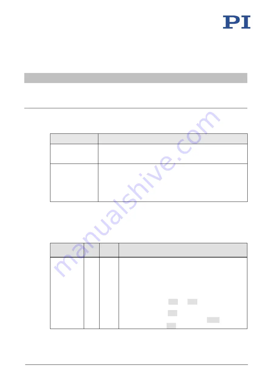
3.5.3
Commandable Elements
The following table contains the elements that can be commanded with GCS commands (p.
125).
Element
Num
ber
Identifi
er
Description
Logical axis
1
1
(modifi-
able)
The logical axis represents the motion of the positioner in the
firmware of the C-863.12. It corresponds to an axis of a linear
coordinate system.
All commands for the motion of a positioner refer to logical
axes.
Motion for logical axes is commanded in the firmware of the
C-863.12 (i.e., for the directions of motion of a positioner).
The motion commands
MOV
and
MVR
are for example,
available in closed-loop operation. The motion command for
open-loop operation is
SMO
.
The axis identifier can be queried with the
SAI?
command
and modified with the
SAI
command. It can consist of up to