


2
www.phywe.com, © All rights reserved
12913-00 / 0222
3 FUNCTIONAL AND OPERATING ELEMENTS
3.1 Operating elements
The sensor has an on-button and two LEDs for indicating the
Bluetooth and battery charge status.
On-button
Press the on-button for more than 3 seconds to switch the
sensor on and off
Bluetooth-LED
Flashing red every 2 seconds
Not connected
Flashing green every 2 seconds
Connected to the ter-
minal device
Flashing green every 4 seconds
Running measurement
Battery charge LED
Flashing red every 5 seconds
Low battery
3.2 Measurement inputs
On the front side of the sensor there is a BNC connector to
which the supplied ammonium ion-selective electrode (PNH
3
-
2-004) can be connected.
4 NOTES ON OPERATION
The device fulfils all of the technical requirements that are
compiled in current EC guidelines. The characteristics of this
product qualify it for the CE mark.
This instrument is only to be put into operation under special-
ist supervision in a controlled electromagnetic environment in
research, educational and training facilities (schools, universi-
ties, institutes and laboratories).
The individual connecting leads are each not to be longer
than 2 m.
The instrument can be so influenced by electrostatic charges
and other electromagnetic phenomena (HF, bursts, indirect
lightning discharges) that it no longer works within the given
specifications. Carry out the following measures to reduce or
eliminate the effect of such disturbance: Ensure potential
equalization at the PC (especially with Laptops). Use screen-
ing. When a total failure of the instrument occurs, unplug it
and plug it back in again for a reset.
5 HANDLING
This section describes the start-up of the sensor and the re-
cording of measurement data. Please read this section thor-
oughly in order to avoid failures or operating errors.
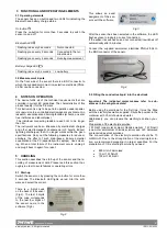
5.1 Start-up
Switch the sensor on by pressing the on-button for more than
3 seconds. The Bluetooth LED lights up red. Star the soft-
ware and select the sensor.
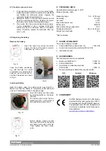
There is a 9-digit code
on the back of the sensor
(Fig.2). The last 4 digits
of the code corresponds
to the last four digits of
the sensor name in the
software (Fig.3).
Fig.2
This allows an exact
assignment of the sen-
sors with the software.
Fig.3
After the sensor has been selected in the software, the LED
flashes green to indicate a correct connection.
If the sensor is switched on and not connected, it switches off
automatically after 5 minutes.
Connect the supplied ammonium electrode PNH
3
-2-004 to
the BNC connector of the sensor.
Fig. 4
5.2 Filling the conductive liquid into the electrode
Important: The indicated molar masses refer to sub-
stances in the anhydrous state!
Before using the electrode for the first time, it must be filled
with the electrolyte solution supplied. Dilute the powder in the
container with 30 ml of deionised water.
Alternatively, you can prepare the electrolyte solution your-
self.
Preparation of the electrolyte solution:
1 M NaCl (one-molar sodium chloride solution), 1 M NH
4
Cl
(one-molar ammonium chloride solution) and H
2
0 deionised
are required as stock solutions.
The concentration of the electrolyte solution should be 10
mM NH
4
Cl. Due to the strong dilution of the electrolyte solu-
tion, we recommend preparing it in larger quantities. For the
preparation of 1 litre electrolyte solution you need:
•
890 ml H
2
0 deionised
•
10 ml 1 M NH
4
Cl
•
100 ml 1 M NaCl


