Extreme. Precision. Positioning.
MANUAL 2107-A005 EN
Ministep Power Stage for Bipolare Control Mode
MSX
MINI
Page 1: ...Extreme Precision Positioning MANUAL 2107 A005 EN Ministep Power Stage for Bipolare Control Mode MSX MINI...
Page 2: ...phytron 03 2018 Manual MA 2107 A005 EN MSX 152 120 MINI Stepper Motor Power Stages for Bipolar Control Mode...
Page 3: ...ed in this manual is correct to the best of our knowledge and belief but cannot be guaranteed Furthermore we reserve the right to make improvements and enhancements to the manual and or the devices de...
Page 4: ...able 26 7 Rotary Switches and DIP Switches 27 7 1 Motor Current Rotary Switches 28 7 2 Step Resolution and Current Shape Rotary Switch 29 7 3 DIP Switches 29 8 Inputs 30 8 1 MSX 5 V Standard and MSX 5...
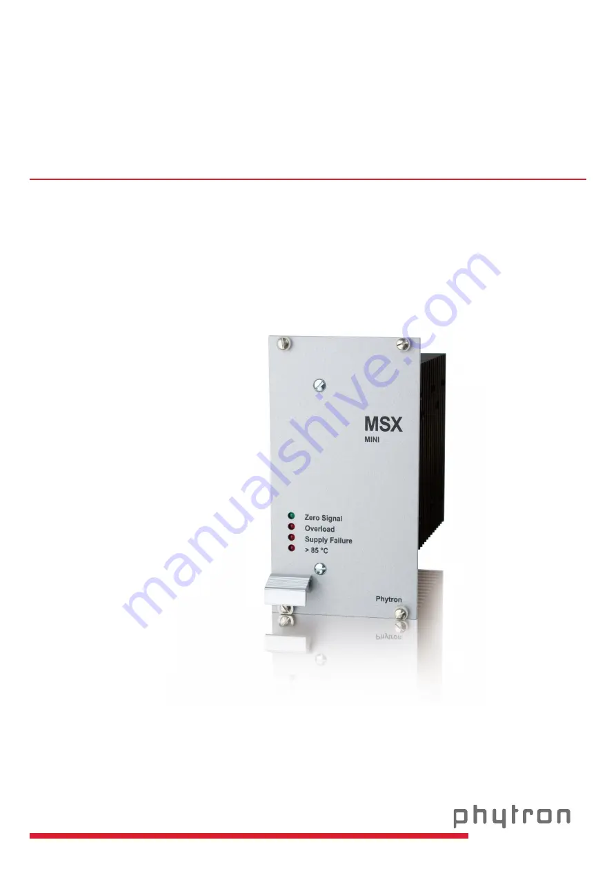
Page 5: ...nd towards ground 32 pin connector acc to DIN 41612 version D Fig 1 Front view of MSXMINI with panel Ministep power stages for two phase stepper motors The power stages type MSX are used for bipolar c...
Page 6: ...ly changes to the stop current if there aren t any control pulse signals The Boost current 130 of the preset run current can either be activated by the input Boost or is permanently switched on by DIP...
Page 7: ...trolling The inputs are optically insulated from the MSX power supply voltage Reset can be added by plugging the J1 jumper on the board Outputs Both MSX outputs position Basic and Error are optically...
Page 8: ...nt panel 14 HP with handle 10008562 32 pin connector 02000895 G MSX V1 1 adaptor board for easy connecting the MSX with connectors for motor cable signal leads and supply voltage 10008712 Damping SB 2...
Page 9: ...ion D Important The output currents must not exceed 10 Ar m s during continuous operation to avoid overheating of the connector Therefore the BOOST function for phase current increase by 30 must not p...
Page 10: ...an be set by the three setting switches behind the front panel Fig 4 16 stepped rotary switch setting 0 F 1 5 DIP Switches Overdrive Boost Activation and Motor direction can be set by the four DIP swi...
Page 11: ...al load capacitor has dropped under 40 V An electronic current limitation or a not adequate smoothing of the DC voltage can be the reason for a short time break of the supply voltage The rotatory ener...
Page 12: ...phytron 11 MA 2107 A005 EN 1 7 Block Diagram Fig 6 MSX block diagram...
Page 13: ...ping CS BLOW UP Factory settings Rotary switch 6 Half step with DMA without CS Phase currents Run and stop current can individually be set by rotary switches Factory settings Rotary switch run current...
Page 14: ...d the MSX increases the run and stop current by 30 The Boost function can permanently be activated by the DIP switch Activation When the optocoupler is energized the motor current is activated Reset I...
Page 15: ...oling in case of higher operation temperatures Environmental requirements The MSX has been designed for degree of pollution 2 acc to EN 50178 Admissible heat sink temperature max 85 C The power stage...
Page 16: ...ust be constructed with reinforced or double insulation to avoid dangerous touch voltages 50 VAC and 120 VDC in case of an error 3 If you need to remove the front panel or to open the device Up to 3 m...
Page 17: ...on Therefore the motor power stage 0 V and each equipment has to be grounded When protection by automatic disconnection EN 61140 VDE 0100 part 410 is used for power stages with definite voltage 50 VAC...
Page 18: ...cy Change the acceleration frequency Reduce the motor current Resonance effects occur more often in the full step mode If the positioning of the motor is incorrect this may be caused by perturbations...
Page 19: ...Manual MSX MINI MA 2107 A005 EN 18 4 Dimensions Fig 7 Dimensions...
Page 20: ...r rise over 160 V not even for a short time 1 msec If the limits are exceeded the error output opens The drive is deactivated at the same time Fig 8 Mains supply unit A line filter is recommended with...
Page 21: ...uld be followed The transformer must be constructed with reinforced or double insulation The calculation of the fuse F2 depends on the preset phase current and the motor load Withstand voltage 200 V R...
Page 22: ...g Rubycon series BXC 68 F 200 V We recommend to parallel six capacitors with every 68 F 200 V for increasing the life time of the MSX capacitor to get a total of 408 F 200 V 4 Transformer load capacit...
Page 23: ...use of a type SB 234 damping module is recommended If an error signal SUPPLY FAILURE arises prior to any other action check that the supply voltage is within the required nominal range this includes...
Page 24: ...mended If wiring scheme 3 cannot be used because of the motor construction the motor may be operated with only two of the four windings energized according to wiring scheme 4 Warning 5 lead stepper mo...
Page 25: ...bances affecting the wires and instruments installed close to the drive system we recommend to use shielded cables The power supply unit in which the MSX is built in and the motor should be connected...
Page 26: ...phytron 25 MA 2107 A005 EN 6 2 Wiring Schemes Fig 11 Connection diagrams for 4 6 and 8 wire stepper motors...
Page 27: ...oss section of the motor cable 1 50 mm2 For best electromagnetic compatibility EMC you should connect the shielding mesh to the MSX housing Use the cable clamps on the rear side of the MSX power suppl...
Page 28: ...e can be selected by the third one Run and stop current is increased by 30 with Boost Factory settings Rotary switches Position Run current F Stop current 3 Step resolution Current Shape 6 Half step w...
Page 29: ...actory settings The stop current is normally set to 40 50 of the run current to keep the motor temperature as low as possible The table values refer to current values if both motor phases are activate...
Page 30: ...0 without CS B Ministep sinusoidal 1 4 with CS and BLOW UP C Ministep sinusoidal 1 5 with CS and BLOW UP D Ministep sinusoidal 1 10 with CS and BLOW UP E Ministep sinusoidal 1 20 with CS and BLOW UP F...
Page 31: ...T Inputs All inputs include an optocoupler with series resistors 2 x 180 The optocoupler inputs are internally connected via 180 to 5 V The MSX inputs are controlled via open collector The supply volt...
Page 32: ...t value depends on the load torque and the load inertia of the motor shaft If the motor is to be operated above the start stop frequency range the indexer has to generate frequency ramps to accelerate...
Page 33: ...tions to switch the power stage off without having to disconnect it physically from the mains It is possible now to rotate the motor by hand slowly WARNING The Activation input is not in conformance w...
Page 34: ...set to a defined initial state with Reset 0 low active that means that all error messages and the ring counter are reset Then the ring counter is in basic position Both motor phases are energized by t...
Page 35: ...nit is switched on and after a reset Every is generated for the step resolution 4th control pulse Full step 8th control pulse Half step 16th control pulse 1 4 step 20th control pulse 1 5 step 40th con...
Page 36: ...n case of motor short circuit or if the time delay during deceleration is too long The red LED SUPPLY FAILURE shines when the supply voltage is out of the admissible range 40 160 V Danger of destroyin...
Page 37: ...pter The functions Boost Overdrive Current Shaping CS and Current Optimization BLOW UP you ll find in the second part A1 FULL STEP HALF STEP MINISTEP FULL STEP The FULL STEP mode is the operating mode...
Page 38: ...the torque delivered is almost the same Most of the resonance is suppressed The following diagram shows extent and direction of the holding torques of a 4 step motor during one revolution without and...
Page 39: ...NISTEP MODE Various advantages are obtained by the MINISTEP MODE The torque undulation drops when the number of ministeps is increased Resonance and overshoot phenomena are greatly reduced the motor o...
Page 40: ...gs steep ramps the motor current is too high during continuous operation and results in motor overheating However a lower phase current results in too flat acceleration and deceleration ramps Therefor...
Page 41: ...urrent shape Overdrive is activated by DIP switches Fig 22 Phase currents with Overdrive The Overdrive function increases the r m s phase current automatically by a factor of 2 for all frequencies 1 k...
Page 42: ...ows the frequency values for switching on and off the overdrive function with different step resolutions Step resolution Input control pulse frequency Overdrive on at Overdrive off at 1 1 1 kHz 0 9 kH...
Page 43: ...mode Remark The current shape in the Ministep mode with Overdrive is similar to that of the full step mode however in the 1 n Ministep mode the number of pulses necessary to attain the same speed is...
Page 44: ...23 for average speed Fig 24 Current Shaping CS These typical deformations can be observed for all types of curves They are caused by the stepper motor inductance and the generator feedback which incre...
Page 45: ...less differs from this ideal shape Therefore the MSX offers the possibility to select a current shape as shown in figure 24 In function of the motor used it is possible to increase the motor performa...
Page 46: ...ided The current delay time is set to 40 ms Automatic change from run to stop current The ratio between both phase currents remains equal in the respective current feed pattern Changing from run to st...
Page 47: ...he adaptor board includes connectors for motor cable ST4 to ST7 signal lines ST2 and supply voltage ST8 and ST9 The control signals for Open Collector controlling are connected to the ST2 It is possib...
Page 48: ...g or disconnecting the power stage Danger of damage by electric arcing All connectors must only be plugged in or out when the supply voltage is switched off The G MSX adaptor board has to be mounted i...
Page 49: ...wrong wiring C2 ESD Protective Measures All the products which we deliver have been carefully checked and submitted to a longterm test To avoid the failure of components sensitive to electrostatic di...
Page 50: ...phytron 49 MA 2107 A005 EN Appendix D Declarations of Conformity...
Page 51: ...Manual MSX MINI MA 2107 A005 EN 50...
Page 52: ...48 F Frequency 31 Front planel 7 Fuse 20 I Inputs 6 13 Insulation 22 J Jumper 5 32 L Lead cross section 14 26 Load capacitor 21 M Ministep 38 Motor cable 26 Motor direction 13 31 Motor time constant 2...
Page 53: ...Phytron GmbH Industriestra e 12 82194 Gr benzell T 49 8142 503 0 F 49 8142 503 190 www phytron eu...