


PCM-072/phyCORE-AM64xx System on Module
L-860e.A0
© PHYTEC America L.L.C. 2022
53
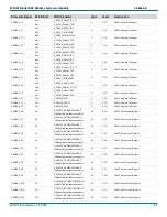
Processor Signal
X1 Pin #(s)
SOM Signal(s)
Type
Level Description
PRG1_IEP0_EDIO_DATA_IN_OUT28
D58
X_CPSW_RGMII1_TX_CTL
2
I/O
3.3V
1
PRU Industrial Ethernet
Distributed Clock Sync Output
PRG1_IEP0_EDIO_DATA_IN_OUT29
D59
X_CPSW_RGMII1_TXC
2
I/O
3.3V
1
PRU Industrial Ethernet
Distributed Clock Sync Output
PRG1_IEP0_EDIO_DATA_IN_OUT30
D62
X_CPSW_RGMII1_TD1
2
I/O
3.3V
1
PRU Industrial Ethernet
Distributed Clock Sync Output
PRG1_IEP0_EDIO_DATA_IN_OUT31
D63
X_CPSW_RGMII1_TD2
2
I/O
3.3V
1
PRU Industrial Ethernet
Distributed Clock Sync Output
PRG1_IEP1_EDC_LATCH_IN1
D61
X_CPSW_RGMII1_TD0
2
I
3.3V
1
PRU Industrial Ethernet
Distributed Clock Latch Input
PRG1_IEP1_EDC_SYNC_OUT1
D64
X_CPSW_RGMII1_TD3
2
O
3.3V
1
PRU Industrial Ethernet
Distributed Clock Sync Output
1
:
The voltage level for this signal is configurable for 1.8V or 3.3V. The default voltage level is listed here, but always check the actual jumper setting for the applicable
SOM configuration. Refer to section
for details
2:
Do not use this signal if the on-board ethernet PHY is populated
7.2.2 Ethernet Design In Guide
7.2.2.1
CPSW_ETH0 Ethernet Design In Considerations
•
Connecting the phyCORE-AM64xx SOM to an existing 10/100/1000Base-T network involves adding an RJ45 and
appropriate magnetic devices in the design. See the reference circuit in section
for an example.
•
Avoid any other signal lines crossing the Ethernet signals.
•
More general differential pair routing guidelines are in section
High-Speed Differential Signal Routing
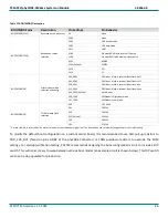
Table 22 phyCORE-AM64xx CPSW_ETH0 Layout Characteristics
Signal Name
Length (µm)
Length
Matching
(µm)
Single Ended
Impedance (Ω)
Differential
Impedance (Ω)
SOM
Trace
Max Total
Max CB
Trace
X_CPSW_ETH0_A-
8773
101600
92827
254
50
100
X_CPSW
8798
101600
92802
50
X_CPSW_ETH0_B-
10755
101600
90845
254
50
100
X_CPSW
10709
101600
90891
50
X_CPSW_ETH0_C-
13191
101600
88409
254
50
100
X_CPSW
13080
101600
88520
50
X_CPSW_ETH0_D-
15842
101600
85758
254
50
100
X_CPSW
15872
101600
85728
50
7.2.2.2
RGMII Design In Considerations
•
Place the Ethernet PHY as close as possible to the SOM connector and keep the trace lengths of the RGMII signals
as short as possible.
•
Add a 10kΩ pull
-down resistor on any unused input or I/O signal on this interface if it is not connected to a PHY.


