


FASTCAM-512PCI Hardware Manual
- 6 -
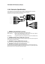
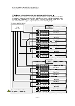
1.2.4. Connector Specifications
In this chapter, the content of the external I/O connector of FASTCAM-512PCI is describes.
The connector and the cable send and receive the following I/O signals.
(Details of the two compound cables are as follows.)
1 GENERAL Output (GEN OUT) Connector
A BNC connector that outputs the following signals under software control.
Expose pos/neg : Outputs a signal that specifies the exposure period of the sensor. Signal is
present during both LIVE display and recording.
Rec pos/neg
:
A signal that specifies the recording process period of the Grabber Board.
2 EXTERNAL SYNC Output (SYNC OUT) Connector
A BNC connector that
outputs the camera’s vertical sync signal to synchronize external equipment
such as strobe unit and pulsed laser.
3 TRIGGER TTL Output (TRIG OUT) Connector
A BNC connector that outputs trigger signal for slaved boards to follow.
4 TRIGGER TTL IN Input (T-TTL IN) Connector
A BNC connector that receives TTL signal from external source to control the start and end of a
recording in currently selected recording mode. Input signal is a pulse of +5V, 5µsec wide, positive
going. Current is 10mA, recommended, and 20mA maximum.
GEN
OUT
T-SW IN
SYNC IN
T-TTL IN
TRIG OUT
SYNC OUT
EXT IN
EXT O UT
EXT OUT
EXT IN