background image

D84-P06-01 GB R3 

21/04/2021

www.photowatt.com

10

CORRECT CONNECTION OF PLUG CONNECTORS

• 

Make sure that all connections are safe and properly 

mated. The PV connectors should not be subjected 

to stress from the exterior. Connectors should only 

be used to connect the circuit. They should never be 

used to turn the circuit on and off.

• 

Connectors are not waterproof when unmated. 

When installing modules, connectors should be con-

nected to each other as soon as possible or appropri-

ate measures (like using connector endcaps) should 

be taken to avoid moisture and dust penetrating into 

the connector.

• 

Do not clean or precondition the connectors using 

lubricants or any unauthorized chemical substances.

USE OF SUITABLE MATERIALS

• 

Only use dedicated solar cable and suitable plugs 

(wiring should be sheathed in a sunlight-resistant 

conduit or, if exposed, should itself be sunlight-re-

sistant) that meet local fire, building and electrical 

regulations. Please ensure that all wiring is in perfect 

electrical and mechanical condition.

• 

Installers may only use single-conductor cable listed 

and labeled as USE-2 or PV wire which is 90°C wet 

rated in North America, and single conductor cable, 

2.5-16 mm² (5-14 AWG), 90°C wet rated in other areas 

(i.e. TUV 2PfG1169 or EN 50618 approved), with prop-

er insulation which is able to withstand the maximum 

possible system open-circuit voltage. Only copper 

conductor material should be used. Select a suitable 

conductor gauge to minimize voltage drop and en-

sure that the conductor ampacity complies with local 
regulations (i.e. NEC 690.8(D)).

CABLE AND CONNECTOR PROTECTION

• 

Secure the cables to the mounting system using 

UVresistant cable ties. Protect exposed cables from 

damage by taking appropriate precautions (e.g. plac-

ing them inside a metallic raceway like EMT conduit). 

Avoid exposure to direct sunlight.

• 

A minimum bending radius of 60mm (2.36 in) is re-

quired when securing the junction box cables to the 

racking system.

• 

Protect exposed connectors from weathering dam-

age by taking appropriate precautions. Avoid expo-

sure to direct sunlight.

• 

Do not place connectors in locations where water 

could easily accumulate.

5.2

GROUNDING


• 

For grounding requirements in North America, a mod-

ule with exposed conductive parts is considered to 

comply with UL 1703 only when it is electrically ground-

ed in accordance with both the instructions presented 

below and the requirements of the National Electrical 

Code. Any grounding means used with Canadian Solar 

Inc. modules should be NRTL certified to UL 467 and 

UL 2703 standards. Please consult our technical ser-

vice team for the formal approval process.

• 

For grounding requirements in other areas, although 

the modules are certified to Safety Class II, we rec-

ommend them to be grounded and that module in-

stallation should comply with all applicable local 

electrical codes and regulations. Grounding connec-

tions should be installed by a qualified electrician. 

Connect module frames together using adequate 

grounding cables: we recommend using 4-14 mm² 

(AWG 6-12) copper wire. Holes provided for this pur-
pose are identified with a grounding symbol 


(IEC61730-1). All conductive connection junctions 

must be firmly fixed.

• 

Do not drill any extra ground holes for convenience 

as this will void the modules warranty.

• 

All bolts, nuts, flat washers, lock washers and other 

relevant hardware should be made of stainless steel, 

unless otherwise specified.

• 

EDF ENR PWT does not provide grounding hardware.

• 

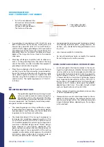
The grounding method described below is recom-

mended for EDF ENR PWT.

Summary of Contents for PW60HT-CB-XF

Page 1: ...INSTALLATION MANUAL OF BIFACIAL MODULES For professional use only...

Page 2: ...CAL SPECIFICATIONS 3 4 0 UNPACKING AND STORAGE 5 5 0 MODULE INSTALLATION 6 5 1 MODULE WIRING 7 5 2 GROUNDING 10 6 0 MOUNTING INSTRUCTIONS 11 6 1 MOUNTING METHODS FOR FRAME BIFACIAL MODULE BOLTING 12 6...

Page 3: ...s pass direct current DC when exposed to sunlight or other light sources Contact with electrically active parts of the module such as terminals can result in injury or death irrespective of whether or...

Page 4: ...to 68 1 02 19 to 15 67 to 59 1 04 14 to 10 58 to 50 1 06 9 to 5 49 to 41 1 08 4 to 0 40 to 32 1 to 5 31 to 23 1 10 1 12 6 to 10 22 to 14 1 14 11 to 15 13 to 5 1 16 16 to 20 4 to 4 1 18 21 to 25 5 to 1...

Page 5: ...ed to moisture or sunlight like using connector endcaps Connector endcaps are available upon request When unloading module pallets from containers please use a fork lift to remove the module pallets a...

Page 6: ...ly specified in the installation instructions and UL2703 certification of the mounting system supplier ENVIRONMENTAL CONDITIONS The module is intended for use in general open air cli mates as defined...

Page 7: ...r optimizing the power generation of the rear side of bifacial modules obstacles between modules and the mounting ground should be avoided as much as possible Constant shading conditions can affect mo...

Page 8: ...PW72LHT CB XF Cable length per lead 1400 mm PW60HT CB XF Cable length per lead 1250 mm NOTICE Adjacent modules in the same row need to be rotated 180 degrees for proper installation Portrait installa...

Page 9: ...mm 1400 mm jumper cable NOTICE Modules in adjacent rows should be rotated 180 degrees for proper installation Portrait installation one row Leap frog for single axis tracker PW72HT CB XF Cable length...

Page 10: ...ties Protect exposed cables from damage by taking appropriate precautions e g plac ing them inside a metallic raceway like EMT conduit Avoid exposure to direct sunlight A minimum bending radius of 60m...

Page 11: ...ating the equivalent maximum authorized design loads Project design loads depend on construction applicable stan dards location and local climate Determination of the design loads is the responsibilit...

Page 12: ...d on actual module frame height For bifacial module with 30 mm frame height our recommended maximum bolt length is 20 mm in order to properly insert the bolts through the mounting hole The system desi...

Page 13: ...r holes installation method B Middle four holes installation method A Middle four holes installation method B PW72HT CB XF PW72LHT CB XF 5400Pa 2400Pa 3600Pa 2400Pa PW60HT CB XF 5400Pa 2400Pa 3600Pa 2...

Page 14: ...alculations and for proper design of support structure The mounting rails shall be designed to limit as much as possible shade on module rear side cells EDF ENR PWT s warranty may be void in cases whe...

Page 15: ...E Module Types Max Mechanical Load Pa 5400 3600 A Range mm PW60HT CB XF 270 380 PW72HT CB XF 410 490 PW72LHT CB XF 410 490 6 2 2 CLAMP MOUNTING ON LONG SIDE OF FRAME AND RAILS PARALLEL TO THE LONG SID...

Page 16: ...d be at least 40mm TRACKER 1P BOLTING METHOD Install and tighten the module clamps to the mount ing rails using the torque stated by the mounting hardware manufacturer M6 X 1 1 4 bolt and nut are used...

Page 17: ...ect modules for cracks damage and loose connections The voltage and current present in an array during daylight hours are sufficient to cause a lethal electri cal shock Ensure that the circuit is disc...

Page 18: ...he existing conditions Method B Wet cleaning If excessive soiling is present on the module surface a non conductive brush sponge or other mild agi tating method may be used with caution Ensure that an...

Reviews: