


RFC 4072R
84 / 128
PHOENIX CONTACT
110146_en_00
7.2.2
User interface
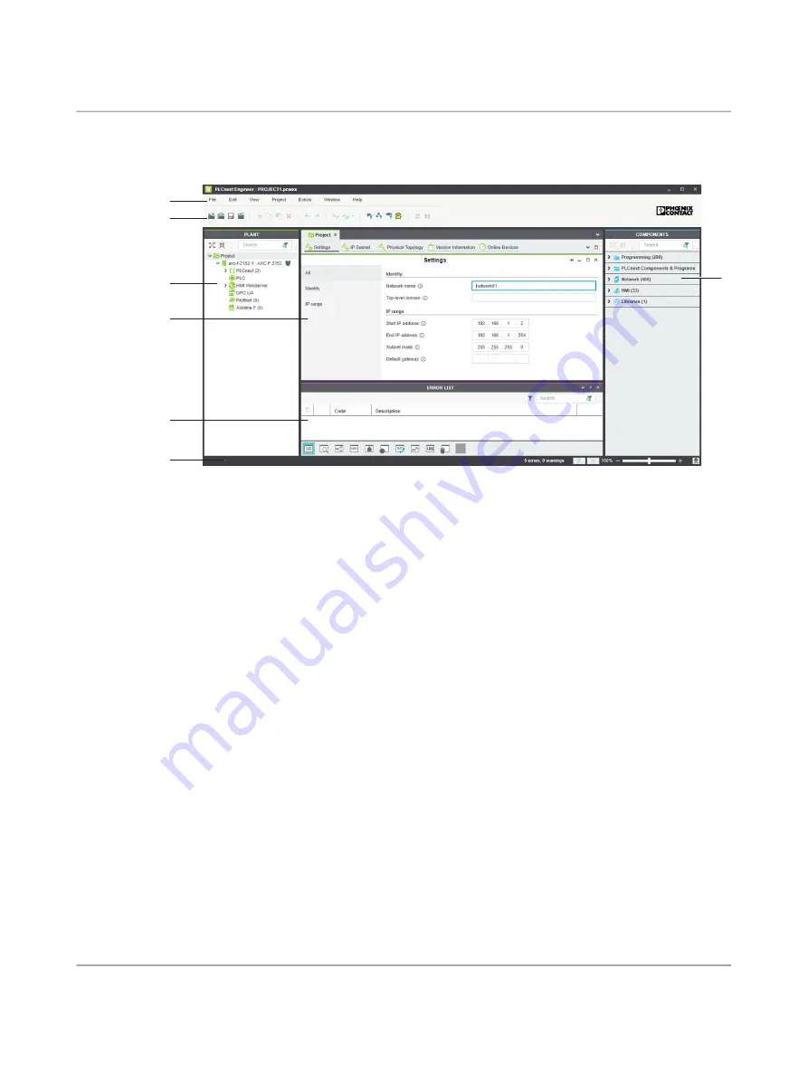
Figure 7
-
1
PLCnext Engineer user interface
1. Menu bar
2. Toolbar
3. “PLANT” area
4. Editor area
5. “COMPONENTS” area
6. Cross-functional area
7. Status bar
“PLANT” area
All of the physical and logical components of your application are mapped in the form of a
hierarchical tree structure in the “PLANT” area.
Editor area
Double-clicking on a node in the “PLANT” area or an element in the “COMPONENTS” area
opens the associated editor group in the editor area. Editor groups are always displayed in
the center of the user interface. The color of the editor group indicates whether it is an in
-
stance editor (green; opened from the “PLANT” area) or a type editor (blue; opened from
the “COMPONENTS” area). Each editor group contains several editors that can be opened
and closed via buttons in the editor group.
“COMPONENTS”
area
The “COMPONENTS” area contains all of the components available for the project. The
components can be divided into the following types based on their function:
– “Programming”
– “PLCnext Components & Programs”
– “Network”
– “HMI”
– “Libraries”
1
2
4
3
6
7
5