background image

Configuration and startup

3886_en_A

PHOENIX CONTACT

35

3.10

Maintenance

Click the “Device Maintenance” tab to access the available maintenance functions of the 

GW PN/ASCII....

3.10.1

Passwords

To change passwords:

1.

Click the “Device Maintenance” page.

2.

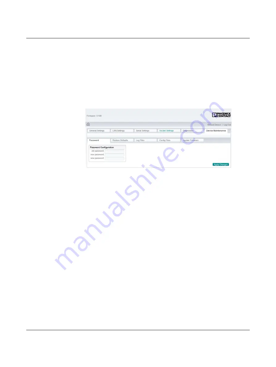
Click the “Passwords” tab to change the password used to access the web server.


Figure 3-18

“Password” page

The GW PN/ASCII... has administrator-level passwords. The administrator-level user 

may make changes to the configuration.

The default user name and password are:

User name: Admin

Password: admin

The “Password” field is case sensitive. The user name is fixed and cannot be modified.

3.

Enter the current password and the new password (twice) in the appropriate fields.

4.

Click the “Apply Changes” button to save changes.

Summary of Contents for 1020882

Page 1: ...User manual Protocol converter for ASCII to PROFINET...

Page 2: ...en_A Protocol converter for ASCII to PROFINET A Designation Order No GW PN ASCII 1E 1DB9 GW PN ASCII 1E 2DB9 GW PN ASCII 2E 2DB9 GW PN ASCII 2E 4DB9 1021080 1021058 1021056 1020882 User manual Revisio...

Page 3: ...guration and startup 15 3 1 Default settings 15 3 2 Web based management 15 3 3 Login 15 3 4 Home screen 16 3 5 General settings 17 3 6 LAN settings 18 3 6 1 IP address 18 3 6 2 Security 19 3 6 3 PROF...

Page 4: ...t submodule data format 41 4 1 1 Data format of an input submodule 41 4 1 2 Data format of an output submodule 41 5 Troubleshooting 43 5 1 Resetting the device 43 5 1 1 Hardware reset 43 5 1 2 Softwar...

Page 5: ...frequency identification RFID tags into PROFINET controllers The family consists of universal RS 232 422 485 one two and four port serial versions with one or two Ethernet ports to fit any applicatio...

Page 6: ...et port and one RS 232 422 485 serial port with a D SUB 9 connector Figure 1 1 GW PN ASCII 1E 1DB9 Table 1 2 GW PN ASCII 1E 1DB9 structure Item Description 1 Power connector 2 P1 D SUB 9 connector 3 E...

Page 7: ...32 422 485 serial ports with D SUB 9 connectors Figure 1 2 GW PN ASCII 1E 2DB9 Table 1 3 GW PN ASCII 1E 2DB9 structure Item Description 1 Power connector 2 P1 D SUB 9 connector 3 Ethernet port RJ45 4...

Page 8: ...D SUB 9 connectors Figure 1 3 GW PN ASCII 2E 2DB9 Table 1 4 GW PN ASCII 2E 2DB9 structure Item Description 1 Power connector 2 P1 D SUB 9 connector 3 Ethernet link status LED 4 E2 Ethernet port RJ45...

Page 9: ...1 4 GW PN ASCII 2E 4DB9 Table 1 5 GW PN ASCII 2E 4DB9 structure Item Description 1 Power connector 2 P3 D SUB 9 connector 3 Ethernet link status LED 4 E2 Ethernet port RJ45 5 Ethernet activity status...

Page 10: ...GW PN ASCII 8 PHOENIX CONTACT 3886_en_A...

Page 11: ...the device yourself but replace it with an equivalent device Repairs may be carried out only by the manufacturer The manufacturer is not liable for any damage caused by violation of the prescribed reg...

Page 12: ...e 1 Use a suitable screwdriver to release the locking mechanism A on the snap on foot of the device 2 Hold on to the device by the housing cover and carefully tilt it upward B 3 Remove the device from...

Page 13: ...a PC Connect the GW PN ASCII to the V 24 RS 232 device to be connected for example a PC by way of the PSM KA 9SUB 9 BB 2 METER V 24 RS 232 cable Order No 2799474 The cable is an interface cable with...

Page 14: ...In RS 485 mode an RS 485 network with several I O devices can be created Use a twisted pair common shielded bus cable to connect the I O devices Connect the individual conductors of the data cable to...

Page 15: ...of the chain so it is recommended to overload and test for performance in the environment The application may also limit the total number of ports that may be installed Some basic guidelines are liste...

Page 16: ...ection CAUTION Incorrect connection may result in damage to equipment and or serious personal injury Only qualified personnel may connect the power start up and operate this device According to the sa...

Page 17: ...lf the current parameters and the operating state are clearly displayed 3 3 Login To log in 1 Set the IP address of the connected PC to the subnetwork of the GW PN ASCII for example IP 192 168 254 10...

Page 18: ...Home screen Advanced settings can be accessed through the menu at the top of the screen The Home screen can be accessed at any time by clicking the Home button in the upper left corner of the web bas...

Page 19: ...the listed information 3 If desired change the listed information The Device Identification group provides fields for entering descriptive information about individual devices Device Name Enter a name...

Page 20: ...P address If a DHCP server assigns IP addresses click the Automatic address assignment DHCP button If using static IP addresses click the Manual address assignment button and enter the appropriate inf...

Page 21: ...crypt traffic on SSL TLS connections that use RSA encryption during handshaking It is used to sign the RSA server certificate in order to verify that the GW PN ASCII is authorized to use the RSA serve...

Page 22: ...type 4096 16 1000 Using the slot information associated with the alarm the IO controller can start a record data read instruction to retrieve the saved packet for the corresponding port device The GW...

Page 23: ...igure the serial port s The Overview page provides a quick summary of the current configuration of the serial port s 2 Click the appropriate configuration tab to edit the configuration of that port Fi...

Page 24: ...7 or 8 data bits Stop bits Select 1 or 2 stop bits Flow control Available options for RS 232 flow control are hardware RTS CTS software Xon Xoff half duplex and none RS 485 terminating resistor The t...

Page 25: ...The GW PN ASCII looks for this character in the second STX byte only if the length is two bytes Specify a value between 0 and FF in hexadecimal format End transmission ETX When enabled the GW PN ASCI...

Page 26: ...e length is two bytes Specify a value between 0 and FF in hexadecimal format End transmission ETX When enabled the GW PN ASCII adds an ETX end of transmission byte sequence that is configured as one b...

Page 27: ...to each Ethernet TCP IP connection of the GW PN ASCII device Figure 3 11 Socket Settings Overview page 2 To edit the configuration of an Ethernet TCP IP connection click the appropriate Socket Config...

Page 28: ...In the TCP Interface Configuration group specify the TCP settings of the Ethernet port Figure 3 13 TCP Interface Configuration group Port name Enter a label for the port This could correspond to the...

Page 29: ...es a serial packet If none is selected the GW PN ASCII accepts the first byte received after the last End Transmission ETX byte s as the start of the next data packet If one byte is selected the GW PN...

Page 30: ...ASCII appends two bytes Byte 1 Specifies the character that represents the first STX byte The GW PN ASCII appends this byte if the length is one byte or two bytes Specify a value between 0 and FF in h...

Page 31: ...herNet IP ports The values can be reset to zero at any time by clicking the Reset Statistics button 2 Serial Interface group PLC connection status This displays the application relationship number of...

Page 32: ...3 Ethernet Interface group PLC connection status This displays the application relationship number of the current PLC connection Device TCP connection status This displays the information of the devic...

Page 33: ...rface page provides diagnostic information about the PROFINET IO communication to a PLC The values can be reset to zero at any time by clicking the Reset Statistics button Figure 3 15 PLC Interface pa...

Page 34: ...r of errors occurred when reading record data Channel diagnostics added This displays the number of channel diagnostics alarms that have been added Channel diagnostics removed This displays the number...

Page 35: ...itted and received during normal operation To view serial log statistics 1 Click the Diagnostics tab 2 Click the Serial Log tab Figure 3 16 Serial Log page The log format is as follows Pkt N ddd hh mm...

Page 36: ...s Click the Reset Log button at any time to clear the log Figure 3 17 Ethernet Logs page The format is as follows Pkt n ddd hh mm ss mmm Rx Tx data ddd days since last system restart hh hours since la...

Page 37: ...ange the password used to access the web server Figure 3 18 Password page The GW PN ASCII has administrator level passwords The administrator level user may make changes to the configuration The defau...

Page 38: ...return the GW PN ASCII to the original factory defaults including the IP address Figure 3 19 Restore Defaults page 2 Check the Check the box to confirm box 3 Click the Apply Changes button Note that t...

Page 39: ...iles page 2 Click the Save Logfile button to save the log as a text file for future use or review the log in the web browser The log displays information about the device such as when a PC created or...

Page 40: ...ers from applying the system configuration file to an unapproved node to gain access to the network 3 Click the Save Configuration button to open a dialog box where the file name and storage location...

Page 41: ...ck the Browse button and navigate to the file in the Browse dialog box 4 Highlight the file to select it and then click the Close button 5 Click the Apply Changes button to install the firmware NOTE E...

Page 42: ...GW PN ASCII 40 PHOENIX CONTACT 3886_en_A...

Page 43: ...ndicates that the data has been truncated 4 1 2 Data format of an output submodule The output data has the same format as the input data of an input submodule The GW PN ASCII transmits the number of o...

Page 44: ...t that was transmitted To confirm that the last data written to the output data area has been transmitted compare the sequence number of the transmitted output data with the input data of that submodu...

Page 45: ...After a successful reset the module returns to the factory default address 192 168 254 254 5 1 2 Software reset To force a software reset 1 Start the web server and navigate to the Device Maintenance...

Page 46: ...GW PN ASCII 44 PHOENIX CONTACT 3886_en_A...

Page 47: ...17 Figure 3 4 LAN Settings IP Address page 18 Figure 3 5 LAN Settings Security page 19 Figure 3 6 LAN Settings PROFINET IO page 20 Figure 3 7 Serial Settings Overview page 21 Figure 3 8 Serial Setting...

Page 48: ...PN ASCII 46 PHOENIX CONTACT 3886_en_A Figure 3 18 Password page 35 Figure 3 19 Restore Defaults page 36 Figure 3 20 Log Files page 37 Figure 3 21 Config Files page 38 Figure 3 22 Update Firmware page...

Page 49: ...ucture 5 Table 1 4 GW PN ASCII 2E 2DB9 structure 6 Table 1 5 GW PN ASCII 2E 4DB9 structure 7 Section 2 Table 2 1 D SUB 9 to RS 232 pin out 11 Table 2 2 D SUB 9 to RS 422 and RS 485 pin out 12 Section...

Page 50: ...GW PN ASCII 48 PHOENIX CONTACT 3886_en_A...

Page 51: ...oducts in your specific application in particular with regard to observing the applicable standards and regulations All information made available in the technical data is supplied without any accompa...

Page 52: ...oducts Subsidiaries If there are any problems that cannot be solved using the documentation please contact your Phoenix Contact subsidiary Subsidiary contact information is available at phoenixcontact...

Reviews: